Body height adjustable electric bulb for illuminated signs

Inactive Publication Date: 2002-02-05
YU WILLIAM
View PDF13 Cites 65 Cited by
  • Summary
  • Abstract
  • Description
  • Claims
  • Application Information

AI Technical Summary

Problems solved by technology

With such a point-source bulb, the light from ID lamp is not homogeneous, and a troublesome beam spot is observable.
Furthermore, the bulb suffers from high power consumption and short life.

Method used


Image

  • Body height adjustable electric bulb for illuminated signs
  • Body height adjustable electric bulb for illuminated signs
  • Body height adjustable electric bulb for illuminated signs

Examples


Embodiment Construction

The body height adjustable lamp bulb of the present invention is an improvement of the bulb described in the Chinese Patent No. 97204601.1 authorized to the same applicant described above, so the contents disclosed in the Patent, and which are also disclosed in corresponding U.S. Pat. No. 5,921,660, are incorporated by reference herein.

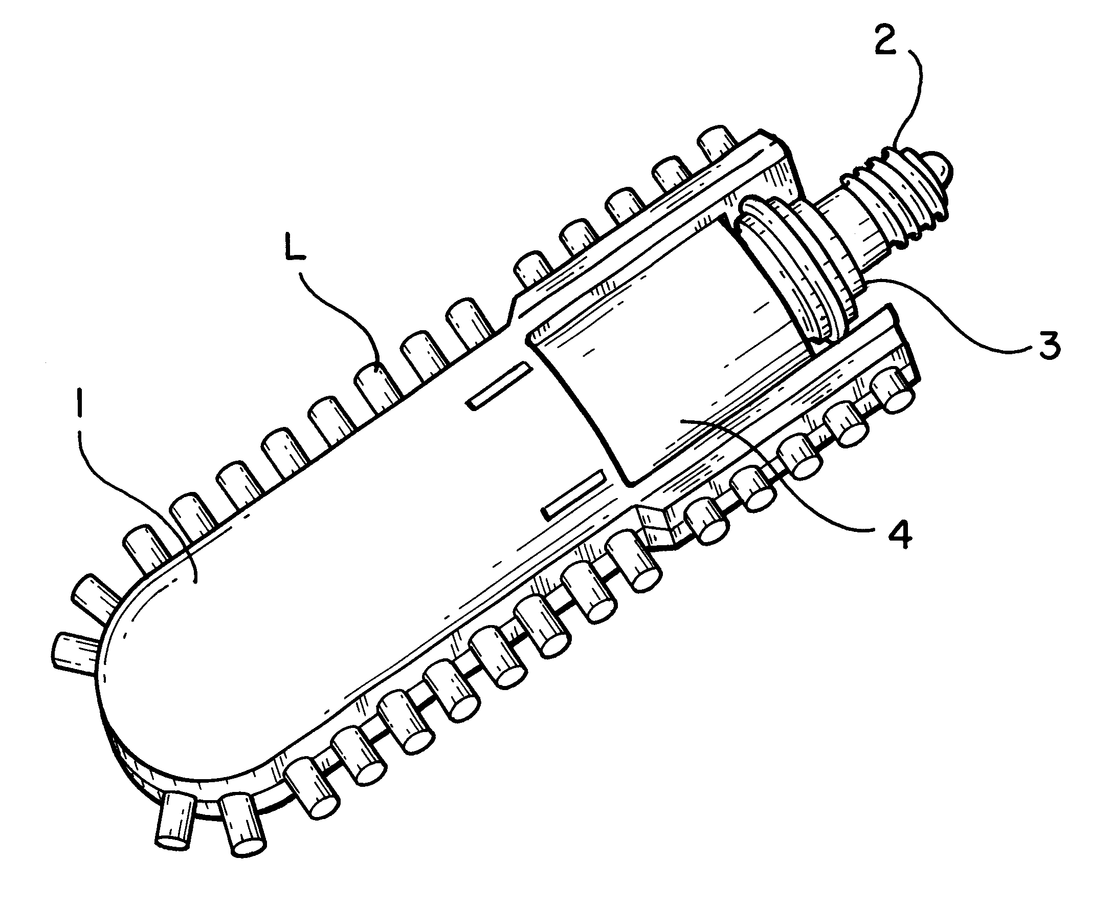
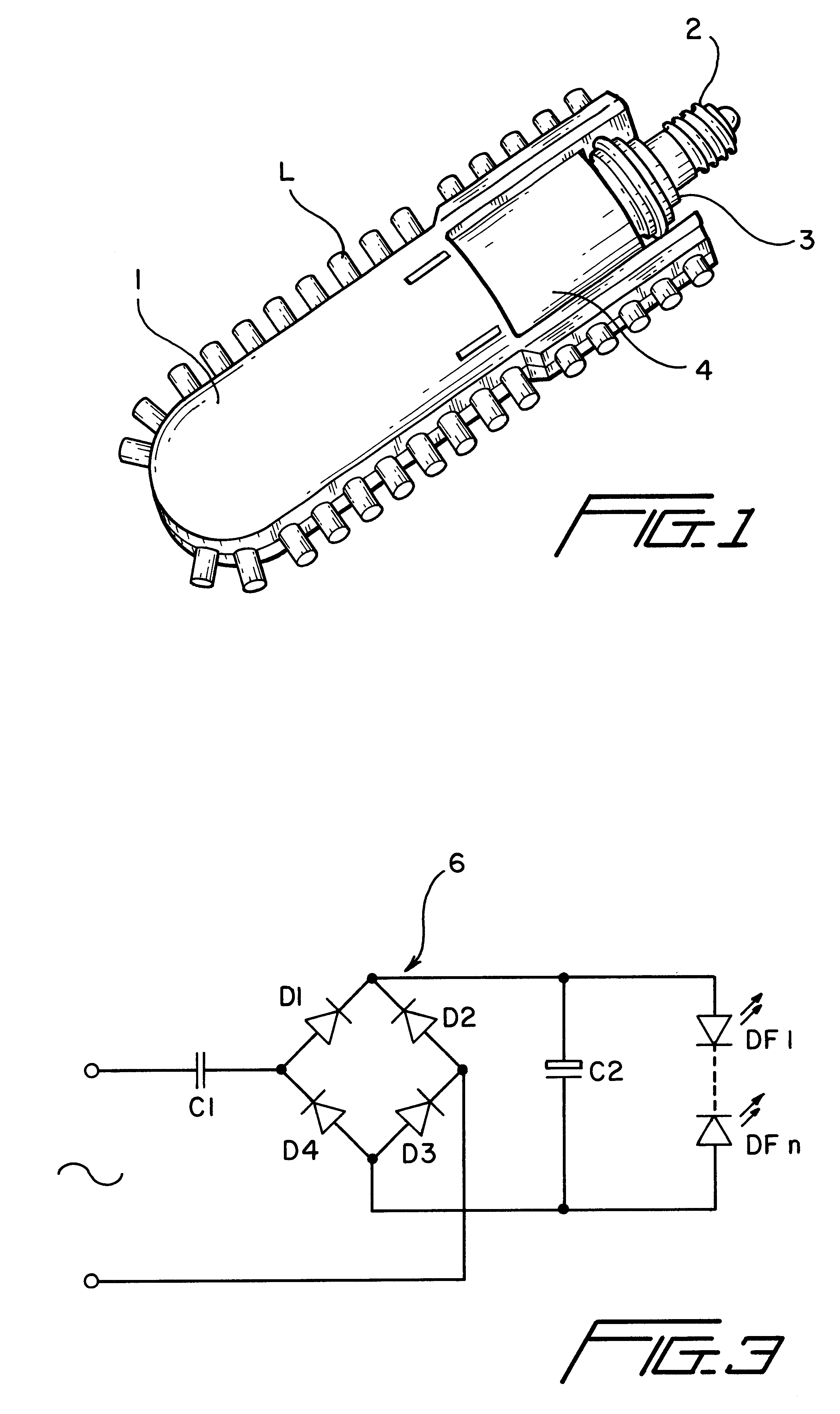
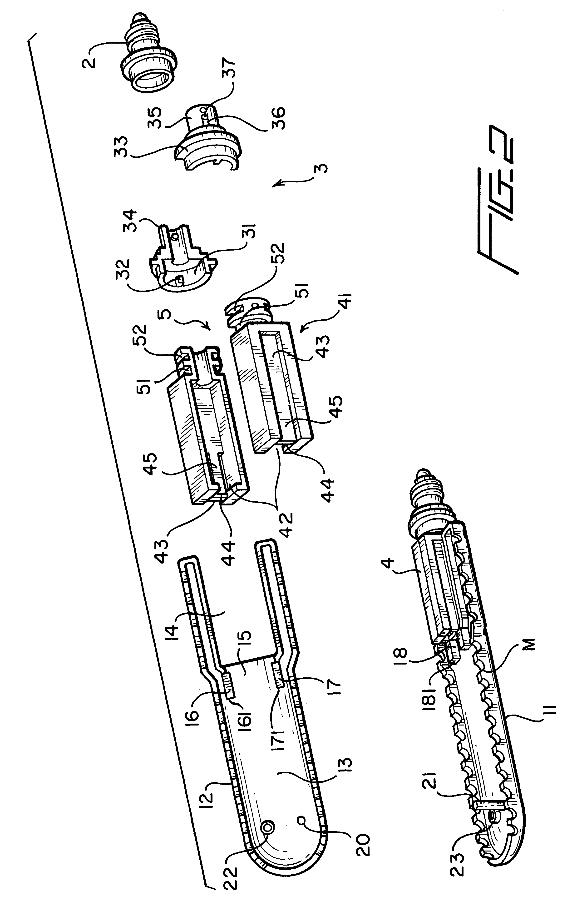
Now, referring to FIG. 1 and FIG. 2, the body height adjustable lamp bulb of the invention comprises a bulb body 1, a bulb head 2, a connector 3, a plurality of LEDs "L" positioned around the periphery of the bulb body 1, and a power supply unit to power the LEDs "L" (referring to FIG. 3 in Chinese Patent No. 97204601.1).

The bulb further comprises a height adjusting unit 4 inserted into an open end of the bulb body 1 with proper friction between them such that the height of the bulb body can be adjusted by a force against the proper friction. The connector 3 is fixed on the bulb head 2 at one end, and another end connects to a joint end 5 of the heigh...


PUM


Abstract

A body height adjustable electric bulb for illuminated sign wherein the bulb comprises a height adjusting unit inserted into an open end of a bulb body against friction between them such that the height of the bulb body can be adjusted by a force against such friction. A connector is fixed on a bulb head and connects to a joint end of the height adjusting unit such that the bulb body can be rotated by a proper torque.

Description

1. Field of the InventionThe invention relates to an electric bulb for an illuminated sign and, in particular, to a height adjustable bulb for an illuminated sign.2. Description of Related ArtGenerally, an identification lamp or illuminated sign comprises a bulb and a flat lantern case or housing for accommodating the bulb to show noticeable identifications created by opening(s) in panels of the housing with emitting and shadowing patterns at both sides.The lamp or bulb known today is conventionally an incandescent bulb. With such a point-source bulb, the light from ID lamp is not homogeneous, and a troublesome beam spot is observable. Furthermore, the bulb suffers from high power consumption and short life.A solution for these problems has been disclosed in China Patent No. 97204601.1, titled "Electric Bulb for Identification Lamp", filed on Jan. 2, 1997 by the applicant and authorized by Chinese Patent Office on Jul. 30, 1998. In such solution, however, the novel bulbs include lig...

Claims


Application Information

Patent Timeline
IPC IPC(8): F21K7/00G09F13/04F21K9/232F21K99/00F21Y107/30F21Y115/10
CPCF21K9/135G09F13/04F21Y2101/02F21Y2111/005Y10S362/80Y10S362/812F21K9/232F21Y2107/30F21Y2115/10
Inventor YU, WILLIAM
Owner YU WILLIAM
Why Eureka
Try Eureka