Digital signal encoding apparatus, digital signal decoding apparatus, digital signal transmitting apparatus and its method

a digital signal and transmitting device technology, applied in the field of digital signal encoding apparatus, digital signal decoding apparatus, digital signal transmitting apparatus and its method, can solve the problems of price rise and complex construction

Inactive Publication Date: 2002-02-19
SONY CORP
View PDF32 Cites 25 Cited by
  • Summary
  • Abstract
  • Description
  • Claims
  • Application Information

AI Technical Summary

Problems solved by technology

Thus, this case has a problem that the construction becomes complicated and the price raises.

Method used


Image

  • Digital signal encoding apparatus, digital signal decoding apparatus, digital signal transmitting apparatus and its method
  • Digital signal encoding apparatus, digital signal decoding apparatus, digital signal transmitting apparatus and its method
  • Digital signal encoding apparatus, digital signal decoding apparatus, digital signal transmitting apparatus and its method

Examples


Embodiment Construction

Preferred embodiments of this invention will be described with reference to the accompanying drawings:

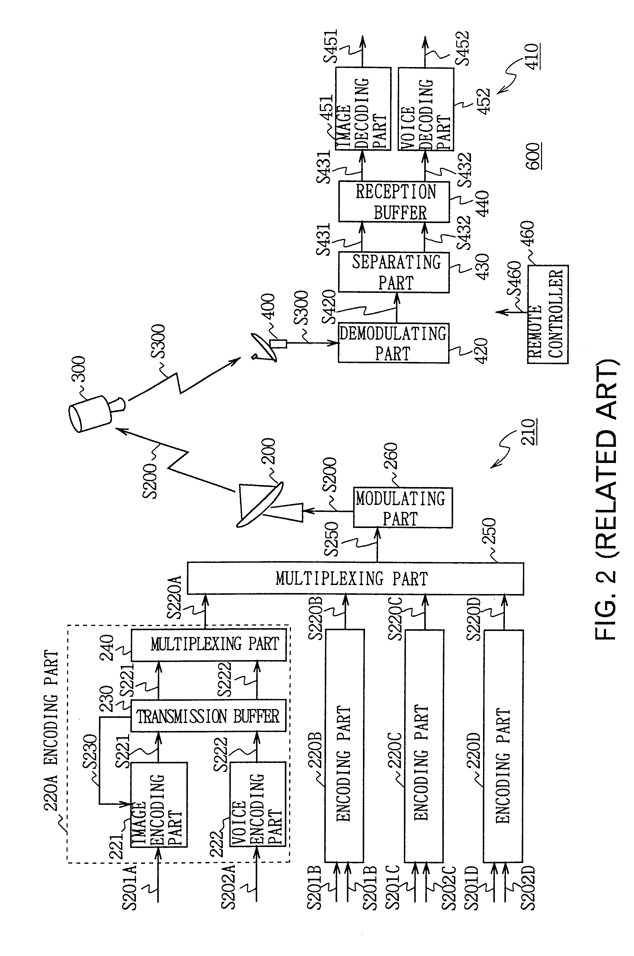
In FIG. 6 symbol 100 denotes a digital satellite broadcasting system as a whole. One channel of HDTV video signal S1H or N channels (here N=4) of SDTV video signals S1A to S1D are supplied alternately from the exterior to an encoding part 20 of an encoding transmitting apparatus 10 in accordance with the broadcasting time slot.

An encoding control part 25 constantly checks the format of the supplied video signal, and outputs a format signal S25 to the encoding part 20 in accordance with the format. The encoding part 20 encodes the HDTV video signal S1H or the SDTV video signals S1A to S1D by the MPEG2 method in accordance with the format signal S25.

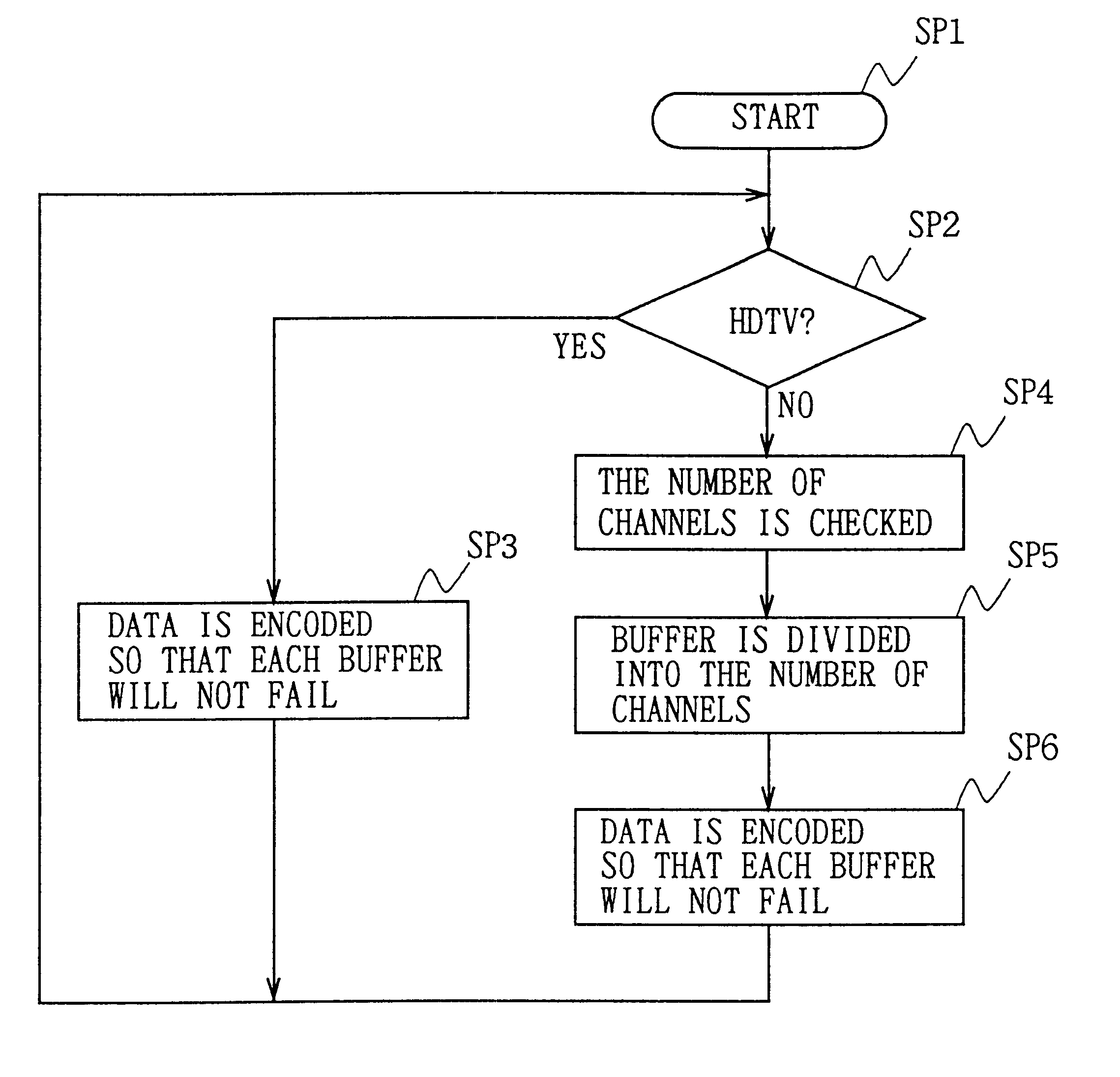
More specifically, FIG. 7 shows the encoding processing in the encoding transmitting apparatus 10. The processing starts at step SP1, and at step SP2, the format of the video signal is judged based on the format signal S25 (FIG. 6). An aff...


PUM


Abstract

In the speckled broadcasting of HDTV and SDTV, an encoding transmitting apparatus and a decoding receiving apparatus can perform a parallel multichannel transmission and reception of SDTV with a simple construction. When an HDTV video signal is encoded and decoded, each of the transmission buffer 30 and the reception buffer 80 is used as a single buffer. On the other hand, when a plurality of SDTV video signals are encoded and decoded, the transmission buffer 30 and the reception buffer 80 are divided into the number of SDTV video signals to use them as a plurality of divided transmission buffers and a plurality of divided reception buffers, so as to perform a encoding and decoding processing.

Description

1. Field of the InventionThe present invention relates to a digital signal encoding apparatus, a digital signal decoding apparatus, a digital signal transmitting apparatus and its method, and more specifically, is applicable to a digital satellite broadcasting.2. Description of the Related ArtA digital satellite broadcasting system using stationary satellite has been started to be used. In FIG. 1, numeral 600 denotes a digital satellite broadcasting system as a whole. A transmission signal S200 transmitted from a transmission antenna 200 is received and amplified by a satellite 300 to be output as a transmission signal S300. The transmission signal S300 is received by a reception antennas 400. Thereby, a broadcasting system having a wide service area which has little reception interference due to obstacles on the ground can be realized. The digital satellite broadcasting system uses an image compressive encoding method called moving picture experts groups (MPEG2) to multiplex a plur...

Claims


Application Information

Patent Timeline
Patent Type & Authority Patents(United States)
IPC IPC(8): H04N7/58H04N7/52H04N7/24H04N5/44H04N11/00H04N19/00H04N7/08H04N7/081H04N19/102H04N19/157H04N19/177H04N19/186H04N19/42H04N19/423H04N19/436H04N19/46H04N19/70H04N21/234H04N21/2365H04N21/434H04N21/44
CPCH04N5/4401H04N21/23406H04N19/436H04N21/4347H04N21/44004H04N21/2365H04N11/002H04N21/426H04N11/24H04N7/015H04N21/433
Inventor TAHARA, KATSUMIKOYANAGI, HIDEKI
Owner SONY CORP
Why Eureka
Try Eureka