Delay tracker

a tracker and delay technology, applied in the field of delay trackers, can solve the problems of lip sync error, constant change of relative delay, and many of the delay of these devices

Inactive Publication Date: 2002-02-26
CASCADES AV
View PDF5 Cites 37 Cited by
  • Summary
  • Abstract
  • Description
  • Claims
  • Application Information

AI Technical Summary

Benefits of technology

Another object of the present invention is to provide an improved apparatus and method for detecting the delays of signals utilizing active portions thereof in order to ensure that the delay tracker passes through the processing means.

Problems solved by technology

A problem exists in many systems when the various primary and related signals are processed (including by transmission and by storage, either direct or indirect, within a facility and / or to / from a facility).
For example, a problem exists in many television facilities when the various video and audio signals are processed within the station (or from facility to facility for that matter).
Many of these devices will have a changing delay as the mode of operation is changed by the operator, as the phase of the incoming video signal drifts with respect to the other video signals or to the systems reference, or otherwise.
However, when the video signal and the auxiliary signals experience relative timing variations due to the changing delays of the different paths, problems occur, the most commonly noticed one being lip sync error when the video is delayed with respect to the audio.
However, the problem in making such corrections arises in detecting the delay of the later (typically video) signal which is output from the system.
This problem is compounded because the relative delay is constantly changing: the delay is often instantly changed as a signal is routed through different processing devices, and different ones of the many input signals are selected to be passed to the output.
However, others might have to wait nearly a whole frame to have their pulse added.
This gives rise to an inherent one frame inaccuracy.
Further, various devices exist which over write or remove the vertical interval, severely compromising the '761's performance.

Method used


Image

  • Delay tracker
  • Delay tracker
  • Delay tracker

Examples


Embodiment Construction

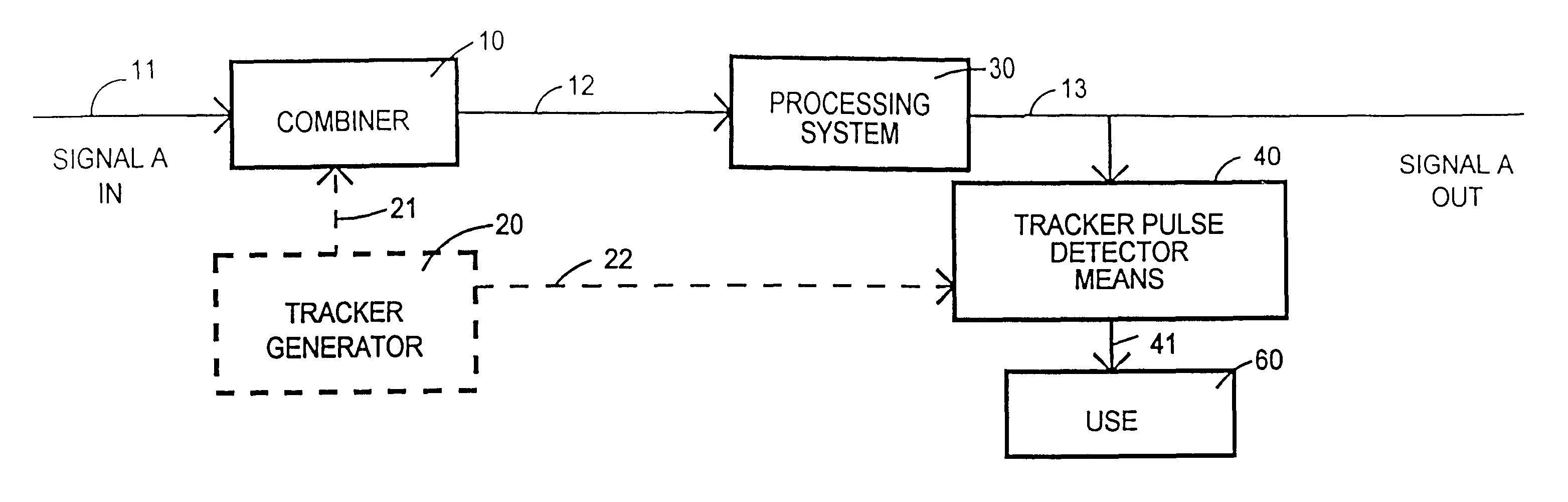
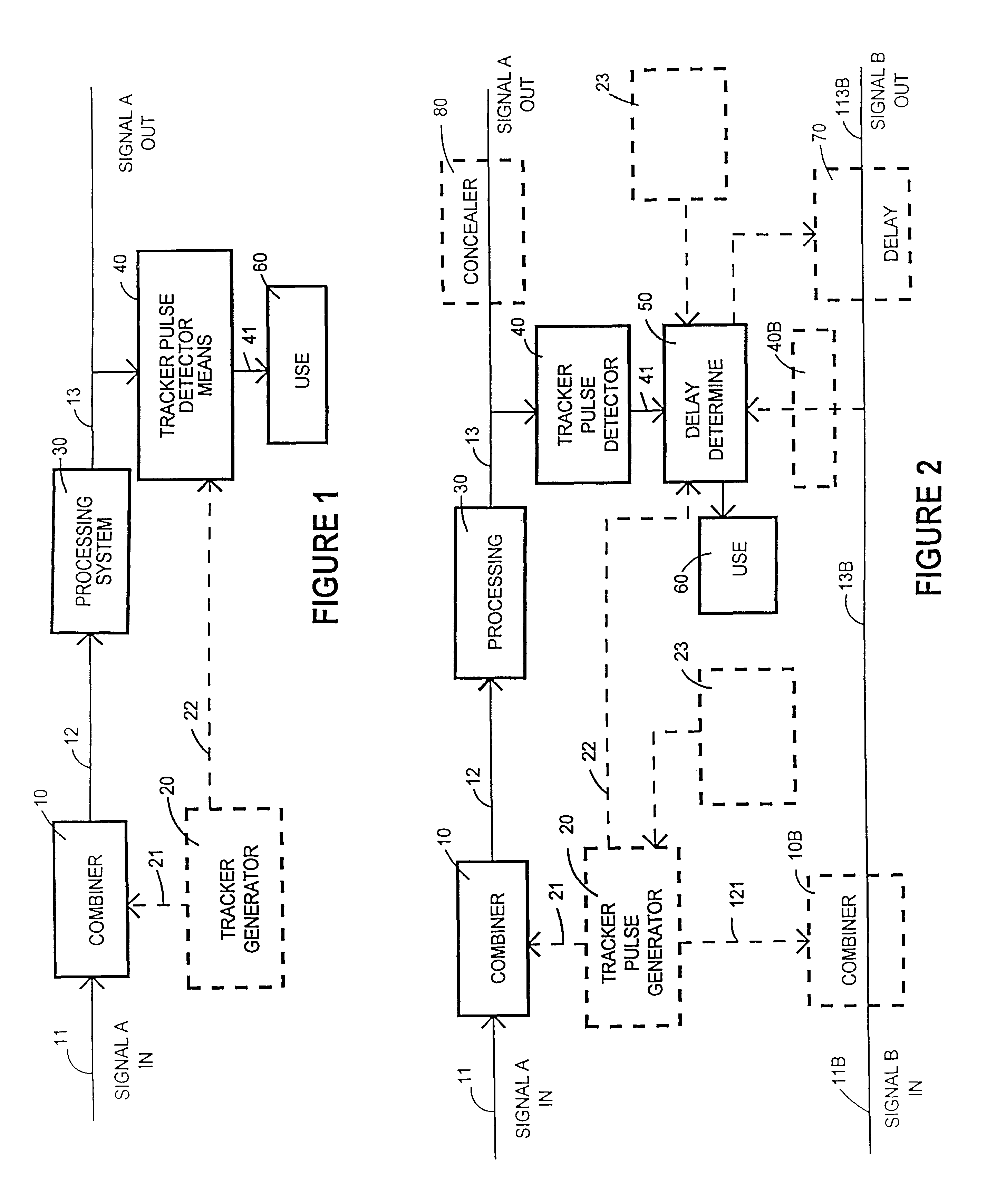
The delay tracker system includes a combiner 10, a tracker pulse generator 20, a processing means 30, a tracker pulse detector 40, a delay determination circuit 50 and a use 60 for the delay established through use of the tracker pulse (FIGS. 1 and 2).

A combiner 10 serves to associate the tracker pulse from the tracker pulse generator 20 with an input signal 11. The input signal may be any type of signal, whether amplitude, frequency, phase, digitally coded, or otherwise existent. This signal 11 includes video signals, audio signals, microwave signals, x-ray signals, digitalized signals (whether by amplitude, width, or other coding technique), and other types of signals having desired information thereon (including timing information). The signals may be single, related multiple signals, unrelated multiple signals, or any combination thereof including series and parallel forms. Further, this signal can be acquired for use and used with the invention at any point during its creation,...


PUM


Abstract

A delay tracker utilizes a special code on the tracked signal in order to recognize such signal and ascertain any delays associated therewith.

Description

This invention relates to a method and apparatus for accurately ascertaining the processing delay of a signal. It is particularly useful for synchronizing a multiplicity of signals, some of which may have passed through processing (including transmission systems) having delays, in order to resynchronize the signals at a known point in time. This application claims priority to the provisional Application 60 / 008,309 filed Dec. 7, 1995--Multiple Video Input Delay Measurement System, J. Carl Cooper inventor.A problem exists in many systems when the various primary and related signals are processed (including by transmission and by storage, either direct or indirect, within a facility and / or to / from a facility). Examples include video systems wherein there are many video and / or audio signal sources from television cameras, tape recorders, direct feeds, remote feeds from microwave and satellite, not to mention what might occur to the signal--noise reduction, synchronizers, transcoders, sw...

Claims


Application Information

Patent Timeline
Patent Type & Authority Patents(United States)
IPC IPC(8): H04N5/067H04N5/073
CPCH04N5/073
Inventor COOPER, JAMES CARL
Owner CASCADES AV
Why Eureka
Try Eureka