
Deterministic task scheduling in a computing device

a computing device and task technology, applied in the direction of multi-programming arrangements, program control, instruments, etc., can solve the problems of consuming a lot of processing time, affecting the active job, and generally not being able to reduce the allocation of resources, so as to prevent the starvation of background tasks

Active Publication Date: 2009-01-15
SHARP KK
View PDF11 Cites 10 Cited by
  • Summary
  • Abstract
  • Description
  • Claims
  • Application Information

AI Technical Summary

Benefits of technology

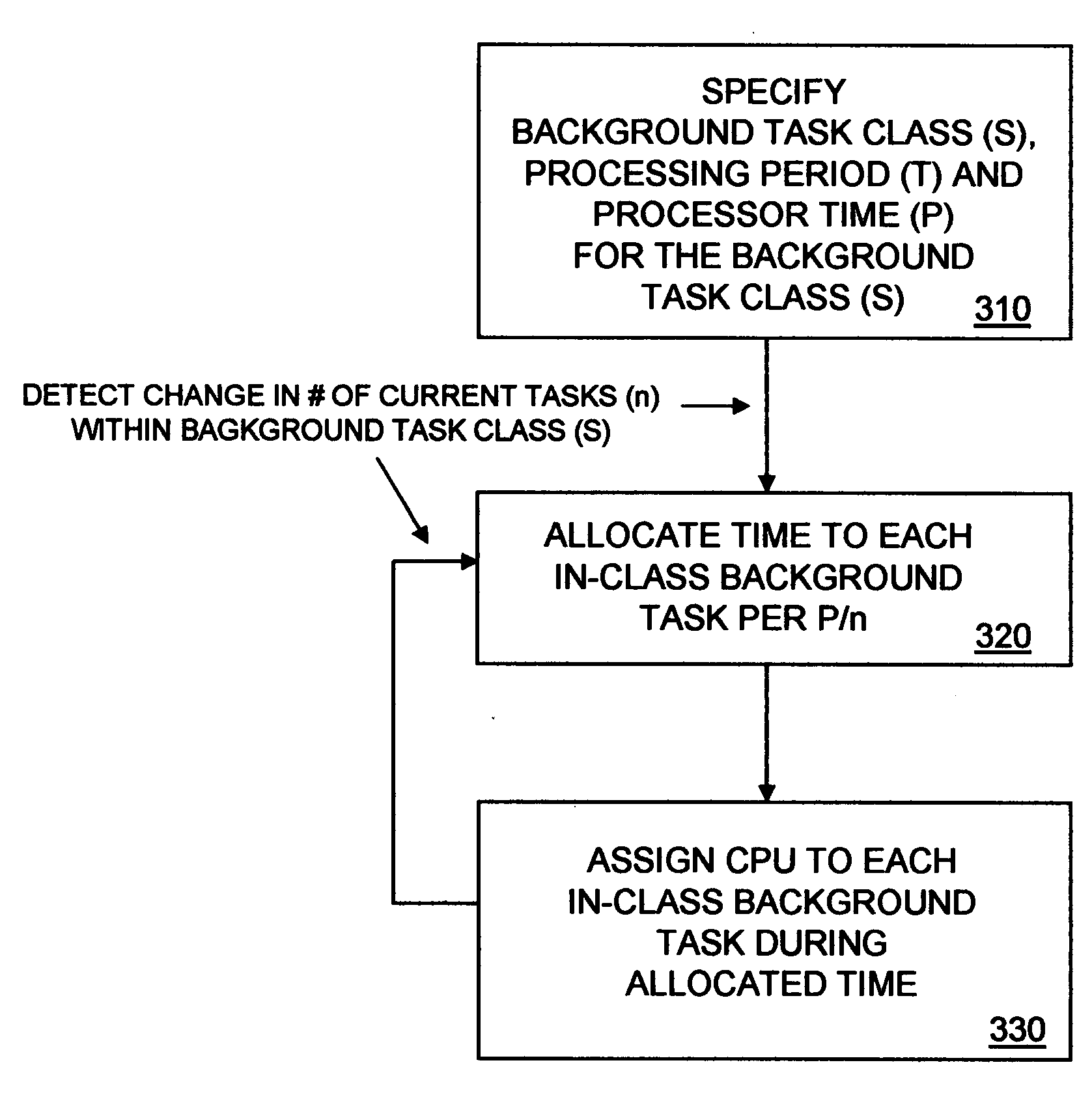
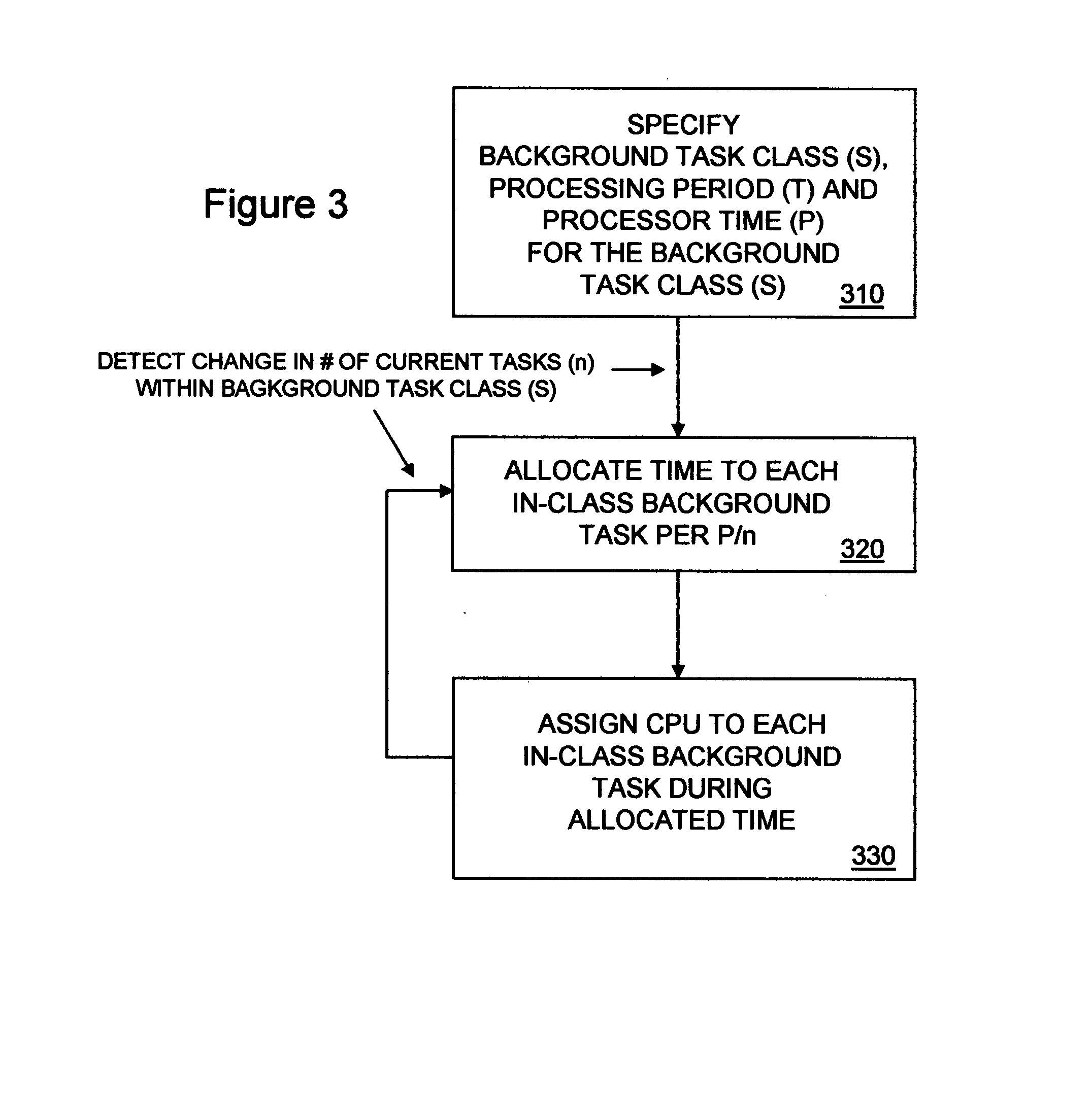
[0004]The present invention, in a basic feature, provides a method and system for scheduling tasks in a computing device in a manner that ensures substantially seamless processing of an active job while preventing starvation of background tasks. In some embodiments, the computing device is a printing device and the active job is an active print job.

Problems solved by technology

If the priority assignment of the background tasks were raised to the same level as the active job tasks (or, conversely, if the priority assignment of the active job tasks were lowered to the some level as the background tasks), the background tasks would receive abundant processing time but would interfere too much with the active job.
While these scheduling algorithms can guarantee that a background task will not be starved-out, they suffer from other problems.
First, these allocations generally cannot be reduced if the processor becomes oversubscribed.
For example, if a second background spooling task is created while a first background spooling task is still pending, these algorithms will generally allocate the same amount of processing time to the second task as to the first, resulting in twice as much processing time being allocated to background spooling and too much interference with an active job.
Second, these allocations are generally monolithic in their use of processing time.
This can lead to a sustained interruption in processing of an active job that is noticeable (e.g. “jerky” execution) and too lengthy from a user's perspective.

Method used


Image

  • Deterministic task scheduling in a computing device
  • Deterministic task scheduling in a computing device
  • Deterministic task scheduling in a computing device

Examples


Embodiment Construction

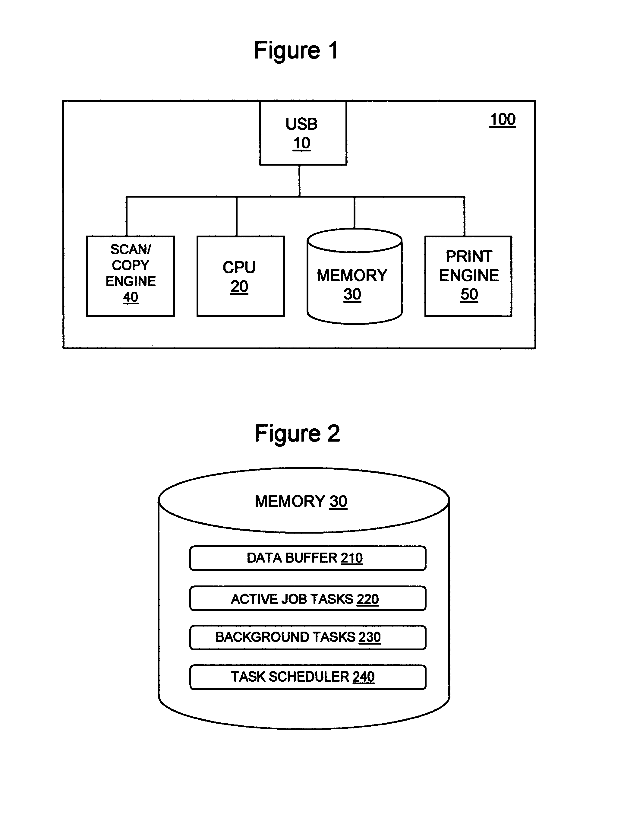
[0014]In FIG. 1, a multifunction printer (MFP) 100 is shown. MFP 100 supports multiple functions, such as printing, scanning and copying. MFP 100 has a universal serial bus (USB) port 10 that communicatively couples MFP 100 with a computing device, such as a personal computer, a workstation or a server, via a USB cable. MFP 100 receives commands and print data via USB port 10. Internal to MFP 100, USB port 10 is communicatively coupled with a processor (CPU) 20, a memory 30 a scan / copy engine 40 and a print engine 50. Scan / copy engine 40 includes scanner / copier logic, such as one or more integrated circuits (ICs), and a mechanical section for performing a scanner and copier functions. For example, scan / copy engine 40 may have a line image sensor mounted on a movable carriage for optically scanning a document under the control of a scanner IC and storing the scanned document into memory 30. Print engine 50 includes printer logic, such as one or more ICs, and a mechanical section for ...


PUM


Abstract

Method and system for scheduling tasks in a computing device in a manner that ensures substantially seamless processing of an active job while preventing starvation of background tasks. In one aspect, a method for scheduling tasks in a computing device comprises the steps of statically allocating processor time (P) to a background task class (S) and dynamically allocating processor time (p) to background tasks within the background task class (S) based at least in part on a current count (n) of the background tasks. The background task processor time (p) may equal the background task class processor time (P) divided by the current count (n). The method may further comprise, in each of successive processing periods, assigning a processor to each of the background tasks for their respective background task processor times (P1-n) and assigning the processor to active job tasks when the processor is not assigned to any of the background tasks. The computing device may be a printing device.

Description

BACKGROUND OF THE INVENTION[0001]The present invention relates to scheduling of tasks in a computing device, such as a printing device and, more particularly, to allocating processing resources in a computing device to tasks in a manner that ensures substantially seamless processing of an active job while preventing starvation of background tasks.[0002]Conventional operating systems for computing devices, such as printing devices, typically schedule tasks based on strict priority and schedule tasks at the some priority round-robin. Under this scheduling algorithm, background tasks, such as background print spooling tasks, typically receive little processing time because they have a lower priority than active job tasks. If the priority assignment of the background tasks were raised to the same level as the active job tasks (or, conversely, if the priority assignment of the active job tasks were lowered to the some level as the background tasks), the background tasks would receive abu...

Claims


Application Information

Patent Timeline
Patent Type & Authority Applications(United States)
IPC IPC(8): G06F9/50
CPCG06F3/1296G06F9/5011G06F9/4881
Inventor OSWALD, TOMMY LEE
Owner SHARP KK
Learn More