Snowmobile four-cycle engine arrangement

a four-cycle engine and snowmobile technology, applied in the direction of machines/engines, vehicle components, transportation and packaging, etc., can solve the problems of two-cycle engines, difficult upright mounting, and increased noise of vibration, so as to simplify communication paths, reduce costs, and connect pipes

Inactive Publication Date: 2006-05-02
SUZUKI MOTOR CORP
View PDF28 Cites 18 Cited by
  • Summary
  • Abstract
  • Description
  • Claims
  • Application Information

AI Technical Summary

Benefits of technology

[0046]Since the heat exchanger is disposed in front of the track, with respect to the vehicle's direction of travel, in the tunnel, it is possible to arrange it close to, and approximately below, the engine. Therefore, the connections such as pipes, etc., can be shortened, thus making it possible to simplify the communication paths so reduce the cost.
[0047]Since the intercooler for cooling the air to be supplied to the engine is put into use as the heat exchanger, it is possible to efficiently cool the air which has been compressed and sent from the supercharger and hence is high in temperature to thereby improve the engine power.
[0048]Since the oil cooler for cooling the engine oil is put into use as the heat exchanger, it is possible to efficiently cool the engine oil which is high in temperature. Therefore, it is possible to prevent oil film starvation hence prevent damage to the engine to thereby maintain the engine in a good running state.
[0049]Since the radiator for cooling the engine cooling water is put into use as the heat exchanger, it is possible to efficiently cool the cooling water which is high in temperature. Therefore, it is possible to prevent the engine from overheating so keep the engine in a good running state.
[0050]Since the oil cooler for cooling the engine oil and the radiator for cooling the engine cooling water are integrated as the heat exchanger, it is possible to eliminate the necessity of providing an oil cooler and radiator separately hence achieve space saving and reduce the number of parts.
[0051]Since a thermostat is interposed in the oil path of the oil cooler, the engine oil can be kept at a proper temperature. Therefore, it is possible to prevent the engine oil from being excessively cooled, hence keep the engine in a good running state.

Problems solved by technology

However, two-cycle engines have drawbacks, when compared with four-cycle engines, of emitting a greater amount of exhaust and louder noise with greater vibrations.
If a four-cycle engine is to be put into a snowmobile in the same manner as above, the upright mounting has been difficult because a four-cycle engine has a greater full height compared to a two cycle engine due to its bulky cylinder head and the necessity of an oil pan.
Further, since a four-cycle engine needs additional unique parts such as an alternator, supercharger, intercooler, oil filter and the like, it has been very difficult to lay out all these parts in a limited engine compartment space.
However, the position at which the intercooler is attached needs careful thought as to the cooling efficiency of the engine and is affected by the attached position of the supercharger, so that it has been very difficult to design the layout and allot mounting spaces for these components in the engine compartment.
Further, there is another drawback that if the snowmobile collides, the front part of the engine compartment will crush to seriously damage the engine.
Further, the underside of the engine compartment for a snowmobile serves as a sled sliding over snow, and therefore needs to be closed, which makes maintenance work such as changing oil difficult.
Therefore, the engine oil increases in temperature due to increased amount of heat from the engine, whereby oil film starvation may occur, leading to damage to the engine.

Method used


Image

  • Snowmobile four-cycle engine arrangement
  • Snowmobile four-cycle engine arrangement
  • Snowmobile four-cycle engine arrangement

Examples


second embodiment

[0097]Next, the present invention will be described in detail with reference to the drawings.

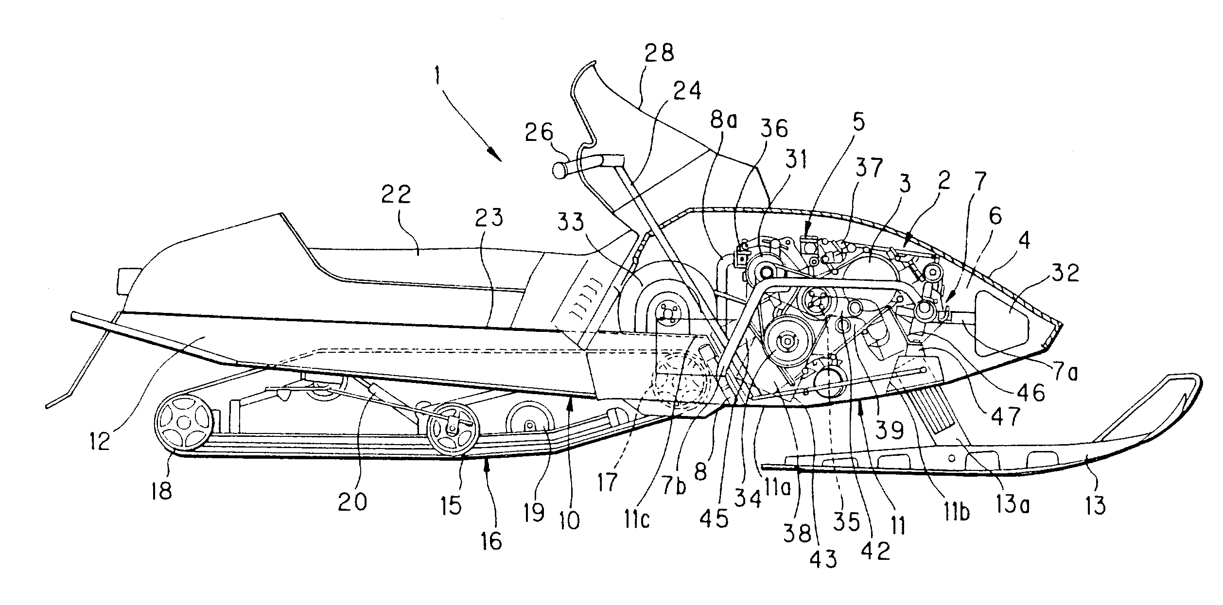
[0098]FIG. 9 is a partially sectional side view showing an overall configuration of a snowmobile four-cycle engine in accordance with the second embodiment of the present invention. FIG. 10 is a partially sectional plan view showing an overall configuration of the same snowmobile four-cycle engine.

[0099]A snowmobile four-cycle engine according to the second embodiment is arranged as shown in FIGS. 9 and 10. That is, similar to the above first embodiment a four-cycle engine 2(to be referred to hereinbelow as engine) having a cylinder head 3 at the top thereof is arranged in an engine compartment 6 enclosed by a front cover 4 on the front body side of a snowmobile 1 and inclined forwards with respect to the vehicle' direction of travel with its crankshaft(not shown) laid substantially parallel to the body width and an intake path 5 on the top of the inclined engine 2 body. A supercharger (turb...

first embodiment

[0100]Here, the configuration of snowmobile 1 is generally the same as that of the first embodiment except in that the rear frame, designated at 12, has a tunnel-like configuration from the body front to the rear, i.e., with the inner side depressed upwards from the bottom, so as to function as a cover accommodating the whole track belt 15 under it.

[0101]As shown in FIGS. 9 and 10, engine 2 is a four-cycle three-cylinder engine having its cylinder head 3 on top and is arranged at the approximate center of engine compartment 6 inside front cover 4 with its crankshaft(not shown) laid substantially parallel to the body width and its cylinder head 3 inclined at a large angle (e.g., more than 45 degrees forwards) in the vehicle's direction of travel. Other arrangement is the same as in the first embodiment.

[0102]In the arrangement of the intake system, the parts on the upper side of engine 2 are positioned under front cover 4 behind the base of windshield 28 from where it extends upward ...

third embodiment

[0116]A snowmobile four-cycle engine is arranged as shown in FIGS. 11 and 12. That is a four-cycle engine 102(to be referred to hereinbelow as engine) having a cylinder head 3 at the top thereof is arranged in an engine compartment 6 enclosed by a front cover 4 on the front body side of a snowmobile 100 and inclined forwards with respect to the vehicle's direction of travel with its crankshaft(not shown) laid substantially parallel to the body width and an intake path 5 on the top of the inclined engine 2 body.

[0117]An oil cooler 108 is arranged at the front side, with respect to the vehicle's direction of travel, in the tunnel that is formed on the inner side of a body frame 10. This oil cooler 108 has a thermostat valve(not shown) between its inlet and outlet oil paths.

[0118]An intake path 5 including a carburetor and throttle body is arranged on the upper side of the engine 102 body an alternator 31 and air cleaner 132 being arranged to the rear, downstream of the intake path.

[0...


PUM


Abstract

A snowmobile four-cycle engine arrangement, includes: a four-cycle engine arranged in an engine compartment formed in the front body of a snowmobile with its crankshaft laid substantially parallel to the body width and having a cylinder case inclined forwards with respect to the vehicle's direction of travel. The engine employs a dry sump oil supplying system and an oil tank separate from the engine is provided. Another snowmobile four-cycle engine arrangement includes: a four-cycle engine having a cylinder head at its top, arranged in the engine compartment and inclined forwards with respect to the vehicle's direction of travel with an intake path provided on the upper portion of the engine body. An intercooler for cooling the intake air is arranged in a tunnel created inside the body frame for accommodating a track belt.

Description

[0001]This application is a Divisional of U.S. patent application Ser. No. 09 / 925,522, filed Aug. 10, 2001, now U.S. Pat. No. 6,561,297, the entire content of which is hereby incorporated by reference in this application.BACKGROUND OF THE INVENTION[0002](1) Field of the Invention[0003]The present invention relates to an engine arrangement, and in particular relates to an arrangement of a four-cycle engine mounted on a snowmobile.[0004](2) Description of the Prior Art[0005]Conventionally, small snow vehicles such as snowmobiles have mainly used two-cycle engines. A two-cycle engine is characterized by a relatively simple engine configuration having the advantages of being lightweight and compact and still providing high power. However, two-cycle engines have drawbacks, when compared with four-cycle engines, of emitting a greater amount of exhaust and louder noise with greater vibrations.[0006]The recent worldwide trend demands a silent, clean and environment-conscious engine. Snow ve...

Claims


Application Information

Patent Timeline
Patent Type & Authority Patents(United States)
IPC IPC(8): B62M27/02F02B75/02
CPCB62M27/02F02B2075/027B62M2027/026B62M2027/023
Inventor YATAGAI, YASUAKIMATSUMURA, HITOSHISHICHI, HIROAKI
Owner SUZUKI MOTOR CORP
Why Eureka
Try Eureka