Digital image orientation marker

a digital image and orientation marker technology, applied in the field of digital radiographic image displays, can solve problems such as inpracticality

Inactive Publication Date: 2002-03-12
DIRECT RADIOGRAPHY
View PDF14 Cites 81 Cited by
  • Summary
  • Abstract
  • Description
  • Claims
  • Application Information

AI Technical Summary

Problems solved by technology

This availability of the image in digital format, however, at times presents certain problems.
This, however is not practical when there is no film present and the image is a sequence of a plurality of numbers stored in a memory.

Method used


Image

  • Digital image orientation marker
  • Digital image orientation marker
  • Digital image orientation marker

Examples


Embodiment Construction

)

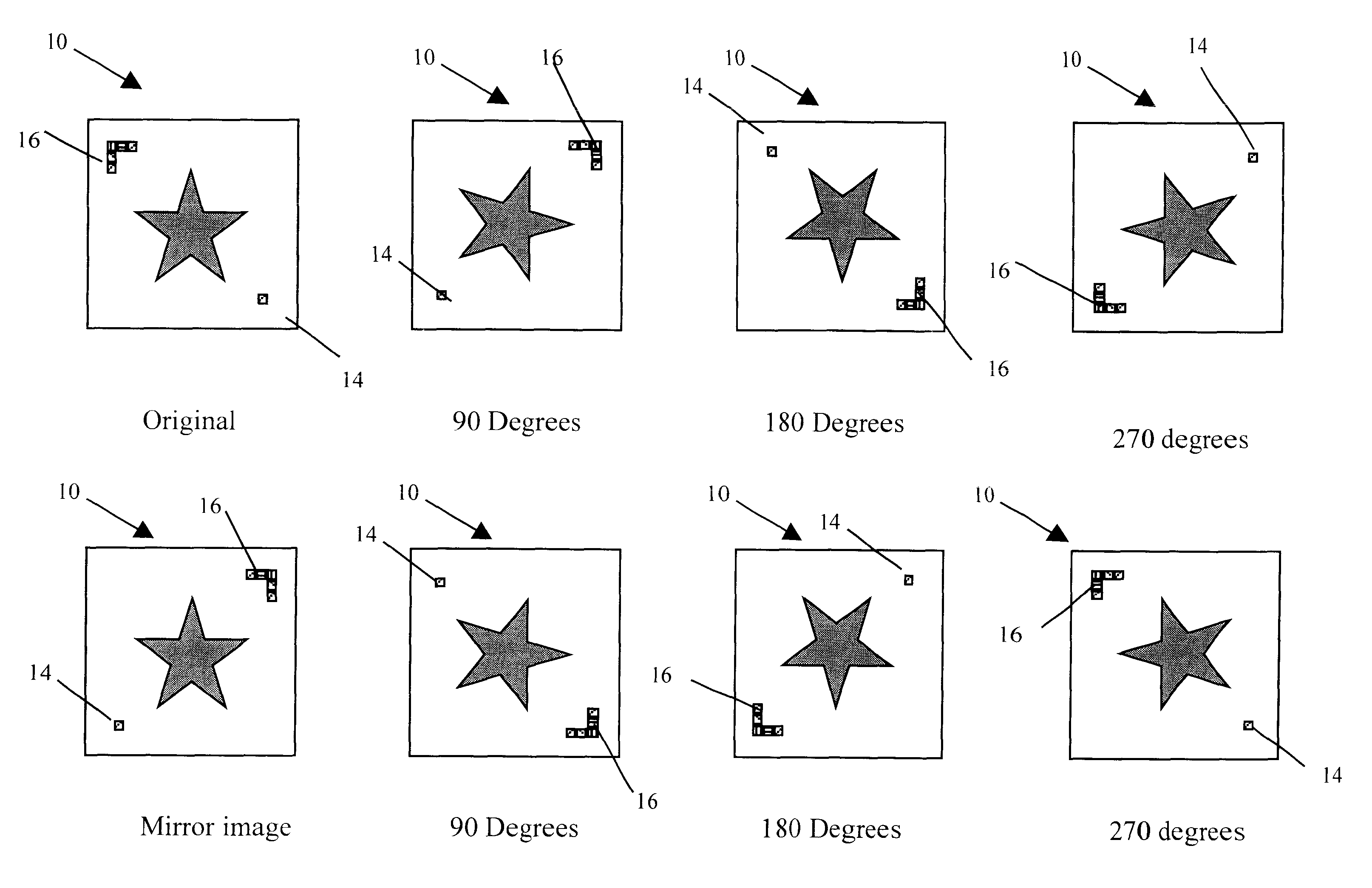
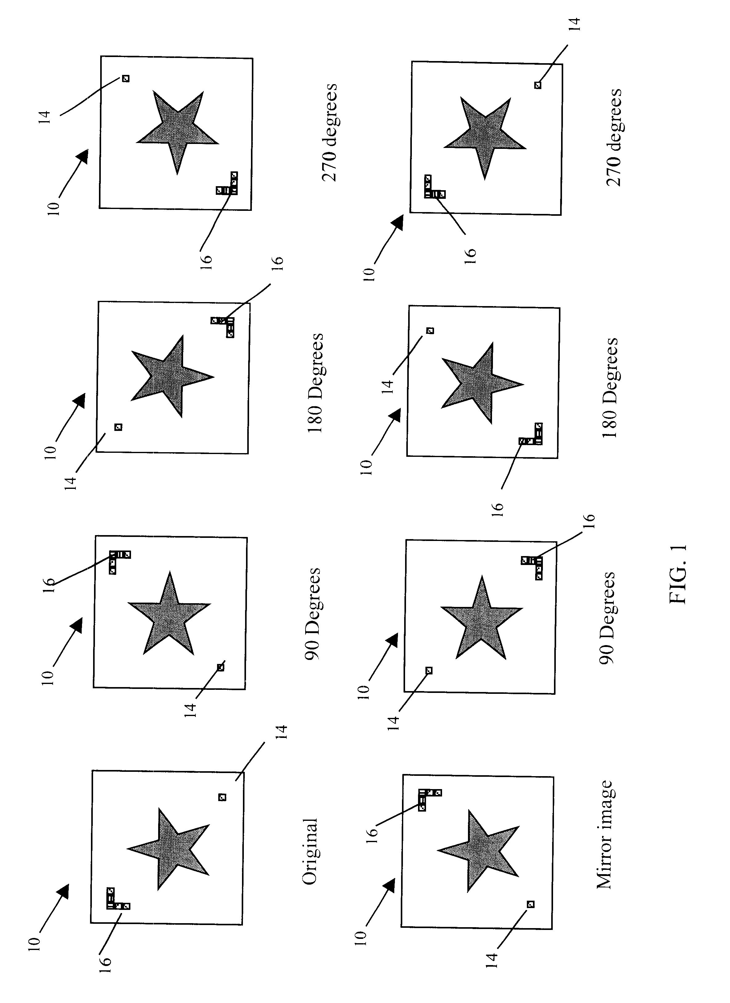
Throughout the following detailed description, similar reference characters refer to similar elements in all figures of the drawings.

The invention is applicable to any digital radiographic system wherein the radiogram is represented by a plurality of stored digital values. Typical such systems employ a digital detector which can be any one of a plurality of known radiographic detectors capable of generating an electrical signal representing impinging radiation intensity variations. Such radiographic detectors are described inter alia in U.S. Pat. No. 5,773,832, issued Jun. 30, 1998 to Sayed et al., U.S. Pat. No. 5,254,480, issued Oct. 19, 1993 to Nang T. Tran, or U.S. Pat. No. 5,315,101, issued May 24, 1994 to Hughes et al. In addition the invention is equally applicable where the digital radiogram is the result of digitization of a traditional film radiogram. Such digitization process is well known in the art and involves scanning a film radiogram and converting it into digital va...


PUM

PropertyMeasurementUnit
sizeaaaaaaaaaa
densitiesaaaaaaaaaa
densityaaaaaaaaaa

Abstract

An orientation marker for a digital radiogram formed by a plurality of pixels arrayed along a plurality of rows and columns. The pixels have densities which represent the radiogram optical density at each pixel point, and the densities are represented by digital values. The marker is made by a number of marker pixels arrayed along at least one row and one column of the radiogram. Each of the pixels forming the marker, have a marker pixel digital value which has been selected to form an asymmetrical marker pixel pattern on the radiogram, replacing the original radiogram pixel values.

Description

1. Field of the inventionThis invention relates to digital radiographic image displays and more particularly to the use of an asymmetrical marker to determine the proper orientation of a displayed digital radiogram.2. Description of Related ArtIn the past decade there has been great progress made in the area of direct radiographic imaging using detectors comprising a two dimensional array of minute sensors to capture a radiation generated image. Information representing an image is captured, often as a charge distribution stored in a plurality of charge storage capacitors in individual sensors arrayed in a two dimensional matrix. We will refer to such detectors generically as direct radiographic detectors to differentiate them from the often referred to as traditional radiographic detectors which employ a photosensitive film usually in combination with an intensifying screen to produce a photographic image of the incident X-ray radiation.The direct radiographic detectors typically c...

Claims


Application Information

Patent Timeline
Patent Type & Authority Patents(United States)
IPC IPC(8): G01N23/02G01N23/04H04N5/232H04N5/32A61B6/00G01T1/161
CPCG01N23/04H04N5/32H04N5/23293H04N23/633
Inventor HUFE, MARK J.WOLFF, DAVID PAULLIU, CHUANDE
Owner DIRECT RADIOGRAPHY
Why Eureka
Try Eureka