Methods and apparatus for swash plate guidance and control

a technology of swash plate and actuator, which is applied in direction controllers, instruments, weapons, etc., can solve the problems of pneumatic or hydraulic cylinders or electric motors, excessive amount of allocated space, and high manufacturing cos

Inactive Publication Date: 2002-03-26
BAE SYST INTEGRATED DEFENSE SOLUTIONS
View PDF9 Cites 26 Cited by
  • Summary
  • Abstract
  • Description
  • Claims
  • Application Information

AI Technical Summary

Problems solved by technology

The problem with the aforementioned devices has been that generally one pneumatic or hydraulic cylinder or electric motor was required for each wing.
The problem with the prior art control devices was that because of the plurality of prime movers required, they were complicated, expensive to manufacture, and frequently used an excessive amount of allocated space.
Additional problems and complications arise when trying to guide and control spin-stabilized objects.
Due to the high rate of objects such as missiles and rounds, the need to keep up with, and control, spinning fins necessitates very high bandwidth and often complicated actuators.
Such actuators may be quite expensive and consume a lot of power--two factors that inhibit the ability to produce low-cost rounds.
In fact, due to limited bandwidth, the maximum spin rate of a missile or round may be established, and indeed limited, by the point at which the actuator can no longer effectively control the missile.
Although these approaches have exhibited some degree of utility, de-spinning an object is not always desirable.
In particular, the de-spinning necessary to achieve control often sacrifices stability that could be provided by a higher, albeit uncontrollable spin rate.
Further, de-spinning wastes critical time, which may limit the ability to steer to close-in targets.

Method used


Image

  • Methods and apparatus for swash plate guidance and control
  • Methods and apparatus for swash plate guidance and control
  • Methods and apparatus for swash plate guidance and control

Examples


Embodiment Construction

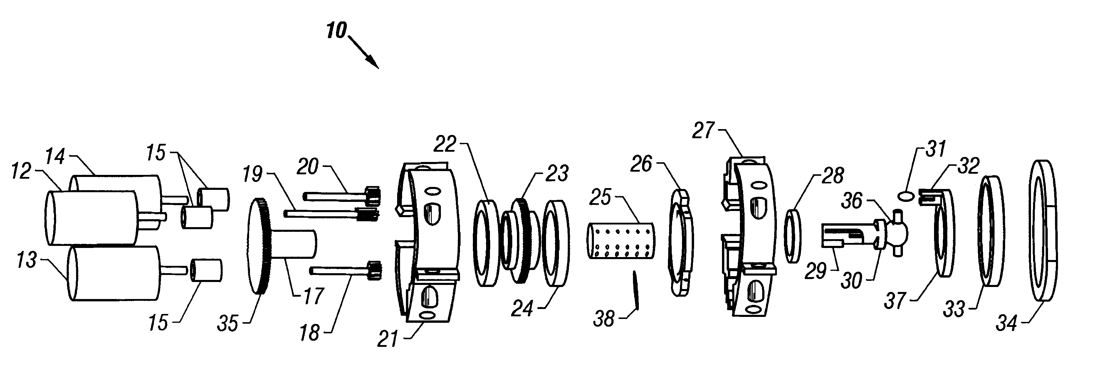
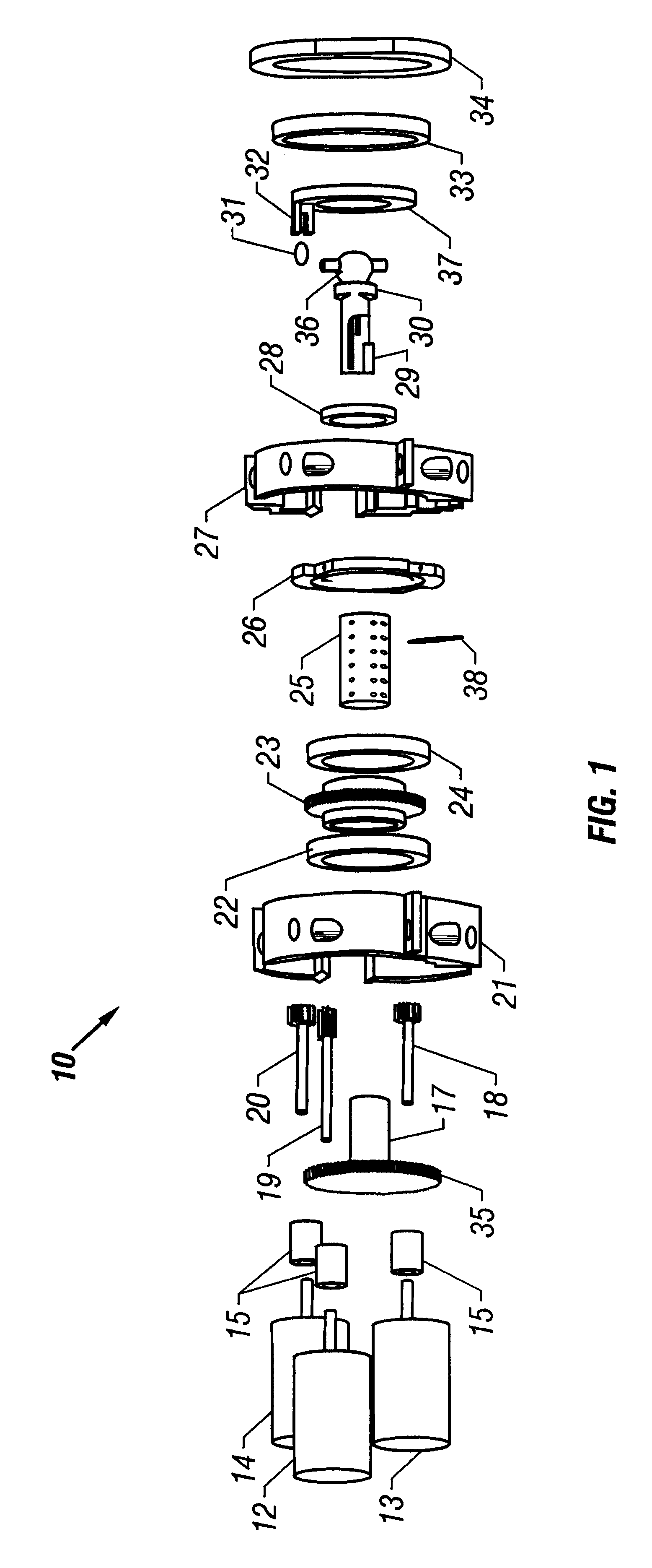
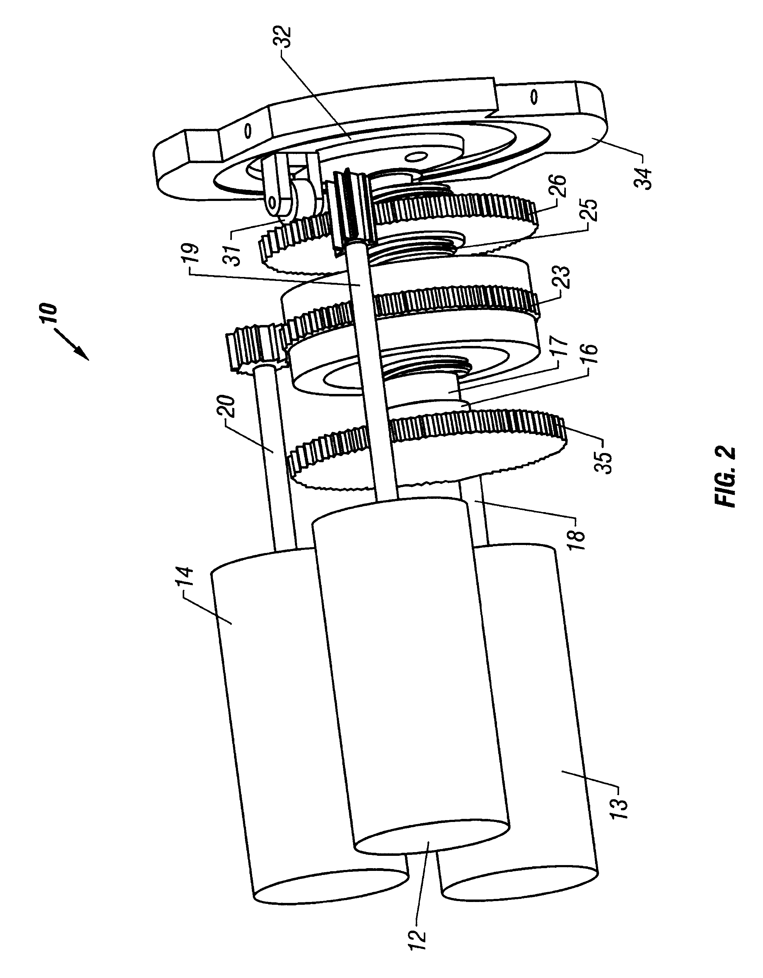
The present disclosure addresses many, if not all, of the limitations mentioned above by providing for methods and apparatuses that allow for the control and guidance of highly spinning objects, while not being unduly limited by actuator bandwidth. In fact, the methods and apparatuses described herein may use low bandwidth actuators and low bandwidth control systems to control highly-spinning objects. Correspondingly, the present disclosure may reduce, or eliminate completely, the need to de-spin an object in order to affect control. In one embodiment, such advantages are accomplished by de-coupling the spin rate of the object being controlled from the bandwidth of the actuator and the control loop--by making the two independent, low-bandwidth actuators may be used. Additionally, the methodology of the present disclosure is advantageous in that it may be implemented with less cost and complexity than previous methods.

Although the applications of the present disclosure are vast, in o...


PUM


Abstract

Apparatuses and methods for controlling an object spinning at a first rate in a first direction. The apparatus includes a swash plate, a rotor, a spin actuator, a roll actuator, and a pitch actuator. The rotor is coupled to the swash plate. The spin actuator is coupled to the rotor and is configured to spin the rotor in a second direction opposite the first direction at a second rate. The roll actuator is coupled to the rotor and is configured to displace the swash plate along a longitudinal axis. The pitch actuator is coupled to the rotor and is configured to tilt the swash plate in a tilt direction about the longitudinal axis, the tilt direction being adjustable by adjusting the second rate relative to the first rate. The roll actuator may be coupled to the pitch actuator so that the pitch actuator keeps a substantially identical orientation with the swash plate as the swash plate is displaced along the longitudinal axis by the roll actuator.

Description

1. Field of the InventionThe present invention relates generally to the fields of guidance and control actuators. More particularly, it concerns swash plate guidance and control actuators that may be used to guide and control spinning objects including missiles and projectiles.2. Description of Related ArtVarious means have been used to guide spinning objects such as non-spin stabilized missiles while in-flight toward their intended targets. A common means for accomplishing in flight guidance in the past has been to include adjustable fins, vanes or wing planes on the projectile. In the past, pneumatic and hydraulic control mechanisms or several electric motors were used to control each pair of wing planes. The problem with the aforementioned devices has been that generally one pneumatic or hydraulic cylinder or electric motor was required for each wing. The problem with the prior art control devices was that because of the plurality of prime movers required, they were complicated, ...

Claims


Application Information

Patent Timeline
Patent Type & Authority Patents(United States)
IPC IPC(8): F42B15/01F42B10/54F42B10/00F42B10/26F42B15/00
CPCF42B10/26F42B15/01F42B10/54
Inventor SALLAEE, BRADLEY T.VINSON, KEN
Owner BAE SYST INTEGRATED DEFENSE SOLUTIONS
Why Eureka
Try Eureka