Virtual image projection device

a projection device and virtual image technology, applied in the field of virtual image projection devices, can solve the problems of difficult to observe the image, the known device suffers from a very tight viewing angle, and the distortion of the three-dimensional depth of the object, so as to achieve the effect of a greater viewing angl

Inactive Publication Date: 2002-04-02
VANTAGE LIGHTING
View PDF18 Cites 41 Cited by
  • Summary
  • Abstract
  • Description
  • Claims
  • Application Information

AI Technical Summary

Benefits of technology

An object of the present invention consists of largely eliminating the above-mentioned disadvantages and providing a virtual image device in accordance with the present invention in which the range of applications for the device is expanded and which ensures an undistorted image reproduction of the subject which is to be depicted, with a greater viewing angle than hitherto.
According to the invention, through the combination of a concave mirror and fresnel lens, the viewing angle can be increased without a costly (oversized) fresnel lens being used as in the prior art, which is desirably 3 times greater than the image which is to be depicted, for the enlargement of the viewing angle.

Problems solved by technology

While suited for their intended purpose, a disadvantage of devices of this type is that only illuminated real objects can be depicted, which is complicated in practice and greatly restricts the use of this image device to objects which can be maintained in the housing.
Whereas flat objects can be depicted with such a device with relatively no difficulty, three-dimensional distortions occur in the depicting of objects with greater three-dimensional depth.
In addition, the observation of the image is substantially limited to a particular viewing axis, which is determined by the foci of the fresnel lens.
In other words, this known device suffers from a very tight viewing angle.
The disadvantages set out above also apply to an alternative embodiment known in which the depiction of the real object takes place by means of a concave mirror arranged in the path of light rays and a partially translucent mirror, instead of with a fresnel lens.
Finally, it is disadvantageous that an observer always has to look into the fresnel lens or into the concave mirror in order to observe the object, which is very disturbing due to the enlargement of the mirror image of the observer.

Method used


Image

  • Virtual image projection device
  • Virtual image projection device
  • Virtual image projection device

Examples


Embodiment Construction

)

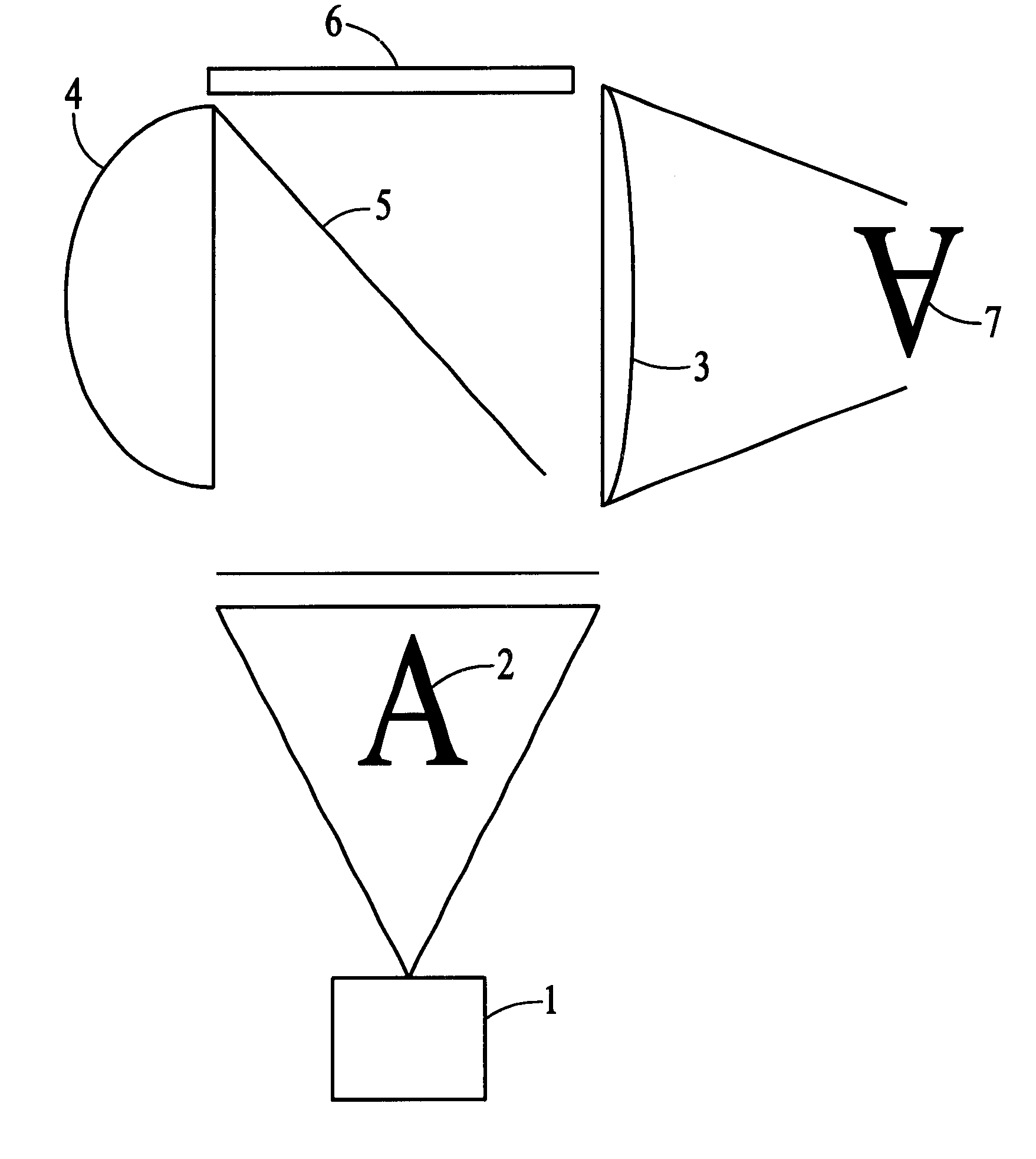
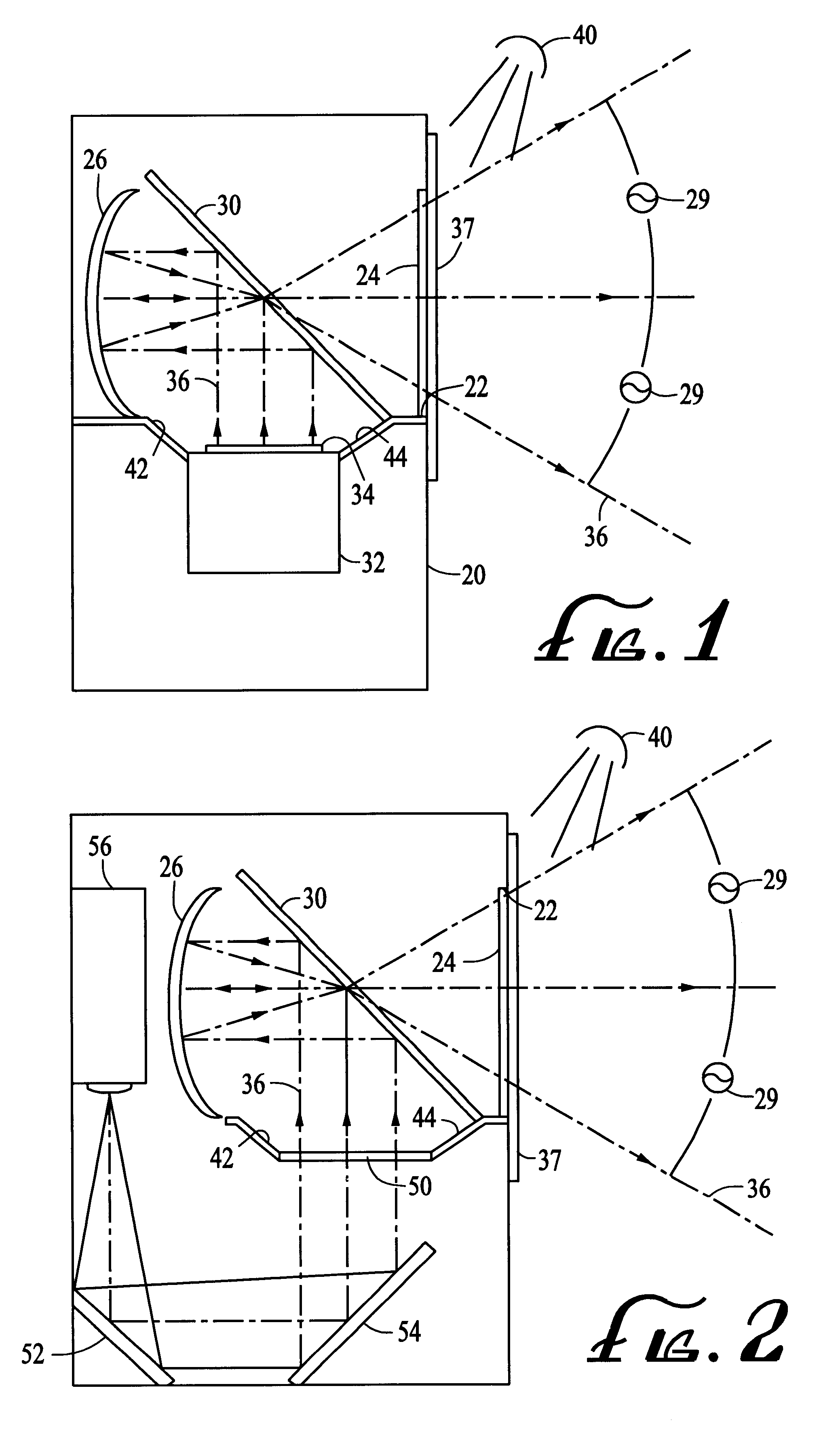
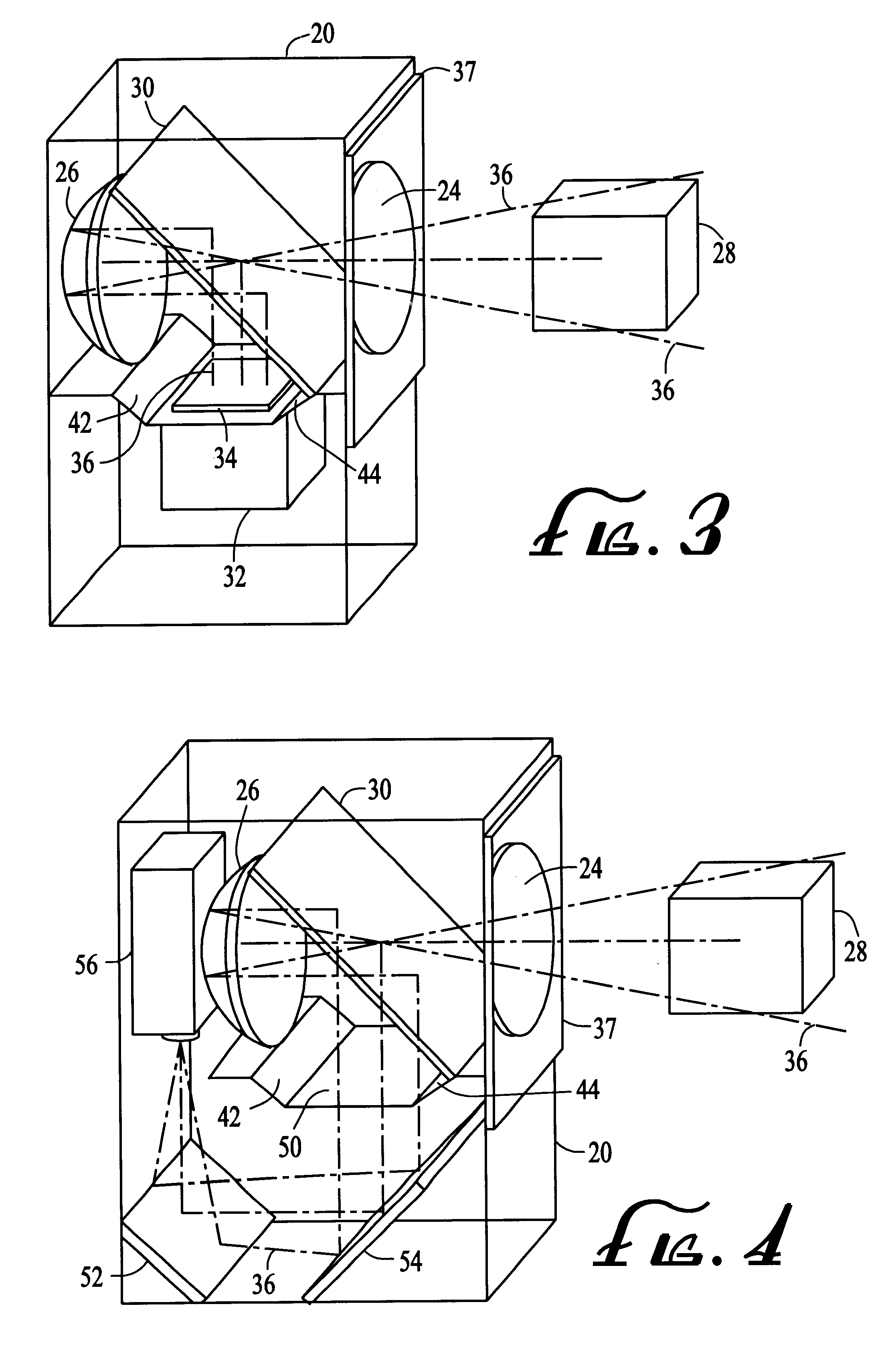
The virtual image production device as shown in FIGS. 1-4 for purposes of illustration, generally includes a chamber or a housing 20, which is closed on all sides and has an observation opening 22 in one wall, which opening is closed by a fresnel lens 24 which runs co-planer to this wall. The fresnel lens 24 is part of an imaging arrangement which in both embodiments of the device shown in FIGS. 1-4 has a concave mirror 26 which is arranged opposite the fresnel lens 24 in the housing 20. A ray divider 30 in the form of a partially translucent mirror is arranged between the concave mirror 26 and the fresnel lens 24.

The imaging arrangement with the elements 24, 26 and 30 produces a virtual image 28 (FIGS. 3 and 4) on the exterior of the housing 20 that appears to an observer (not shown) to be in front of the fresnel lens 24. The field of view of the observer is shown by reference numeral 29 (FIGS. 1 and 2).

In the embodiment of the device illustrated by FIGS. 1 and 3, the image is pro...


PUM


Abstract

The invention relates to a device for the virtual production of an image, with a housing, an image projection device, which produces an image to be displayed. The housing has an observation opening in a wall of the housing with a fresnel lens arranged therein. Imaging optics arranged in the housing for depicting the object onto the fresnel lens. In order to ensure a large range of applications for this device, provision is made that the imaging optics have a concave mirror arranged in the path of light rays between the image projection device and the fresnel lens. The concave mirror lies opposite the fresnel lens and a ray divider is provided therebetween. To increase the illusion effect, a partially translucent mirror (spy mirror) is additionally arranged on the observation side of the fresnel lens.

Description

A. Field of the InventionThe present invention relates to a device for the virtual display of an image. More specifically the present invention relates to a device for the virtual display of moving images such as video, motion pictures and the like.B. Discussion of the Prior ArtDevices are known for the production of a virtual image outside of such devices using an illuminated real object which is included fixedly or rotatably within the devices. In one such device, the virtual image is produced outside the housing by means of a fresnel lens which is arranged in the housing opening. The object can either be arranged lying directly opposite the fresnel lens inside the housing or staggered with respect to the fresnel lens, with the object then being depicted onto the fresnel lens by a suitable mirror arrangement. Such a three-dimensional image device is disclosed in European Patent No. EP-B1-0 410 968 by Raul Orlandi.While suited for their intended purpose, a disadvantage of devices o...

Claims


Application Information

Patent Timeline
Patent Type & Authority Patents(United States)
IPC IPC(8): G02B27/22G03B21/28
CPCG03B21/28G02B27/2292G02B30/56
Inventor KRAUSE, DETLEF
Owner VANTAGE LIGHTING
Why Eureka
Try Eureka