Liquid crystal display apparatus

a technology of liquid crystal display and display screen, which is applied in the direction of optics, polarising elements, instruments, etc., can solve the problems of critical issues such as the degradation the deformation of contrast in the oblique direction, so as to achieve excellent viewing angle compensation, exceptional contrast, and reduce thickness

Active Publication Date: 2006-07-27
NITTO DENKO CORP
View PDF7 Cites 36 Cited by
  • Summary
  • Abstract
  • Description
  • Claims
  • Application Information

AI Technical Summary

Benefits of technology

[0007] The present invention has been made in view of solving the above conventional problems, and an object of the present invention is therefore to provide a liquid crystal display apparatus which allows excellent viewing angle compensation, which exhibits exceptional contrast in an oblique direction, and which can be reduced in thickness.
[0021] In one embodiment of the invention, the color filter is structured to inhibit light scattering from the light source.

Problems solved by technology

However, when conventional retardation plates are used in a liquid crystal display apparatus in a conventional arrangement, contrast in an oblique direction often degrades.
In consideration of such a demand, degradation of contrast in an oblique direction is a critical issue.

Method used


Image

  • Liquid crystal display apparatus
  • Liquid crystal display apparatus
  • Liquid crystal display apparatus

Examples


##tion example 1

PREPARETION EXAMPLE 1

Formation of Optical Compensation Layer

[0115] Polyimide represented by the following formula (6), synthesized from 2,2-bis(3,4-dicarboxyphenyl)hexafluoropropane dianhydride (6FDA) and 2,2′-bis(trifluoromethyl)-4,4-diaminobiphenyl (TFMB), and having a weight average molecular weight (Mw) of 70,000 was dissolved in methyl isobutyl ketone, to thereby prepare a 15 wt % polyimide solution. Preparation of polyimide or the like was carried out by referring to a method described in a document (F. Li et al., Polymer 40 (1999) 4571-4583). Meanwhile, a triacetylcellulose (TAC) film having a thickness of 80 μm was stretched in a width direction 1.3 times at 175° C. through fixed end stretching, to thereby produce a stretched TAC film having a thickness of 75 μm as a substrate film. The polyimide solution was applied onto the substrate film to be dried at 100° C. for 10 minutes. As a result, an optical film A having an optical compensation layer on the substrate film was ob...

preparation example 2

Production of Optical Compensation Element

[0116] A polyvinyl alcohol film was colored in an aqueous solution containing iodine and then uniaxially stretched 6 times between rolls of different speed ratios in an aqueous solution containing boric acid, to thereby obtain a polarizer. The obtained polarizer was laminated on a surface of the substrate film of the optical film A on which the optical compensation layer is not formed. The polarizer was laminated such that a slow axis of the optical compensation layer and an absorption axis of the polarizer were substantially perpendicular to each other. Then, a commercially available TAC film (trade name “UZ-TAC”, available from Fuji Photo Film Co., Ltd.) having a thickness of 40 μm as a protective layer was laminated on a surface of the polarizer on which the optical film A is not laminated, to thereby obtain an optical compensation element B.

example 1

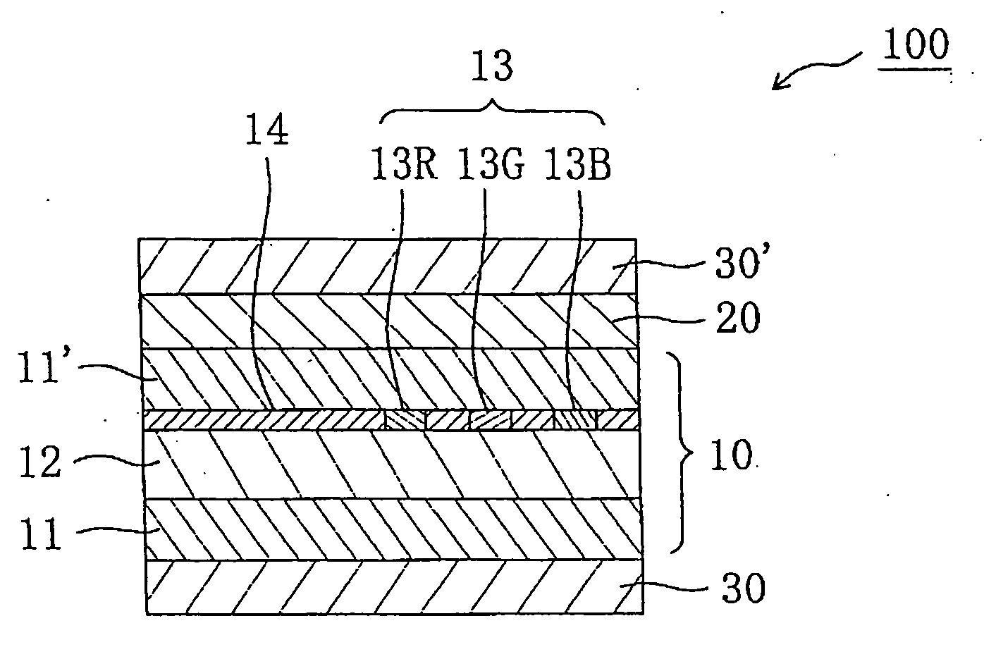
[0117] A liquid crystal cell was removed from a 32-inch liquid crystal monitor LTA260W2-L06 (installed with Patterned-VA liquid crystal cell, manufactured by SAMSUNG). The above optical compensation element B was attached to a viewer side of the liquid crystal cell (that is, the same side as the color filter with respect to the liquid crystal layer) through an acrylic adhesive (thickness of 20 μm) such that the polarizer (actually, TAC protective layer thereof) was arranged on the outer side (viewer side). A polarizing plate (trade name “HEG1425DU”, available from Nitto Denko Corporation) having a structure of TAC protective layer / polarizer / TAC protective layer was attached to a backlight side of the liquid crystal cell through an acrylic adhesive (thickness of 20 μm). A haze value of the substrate provided with the color filter used for the liquid crystal panel was 2.8%. A liquid crystal display apparatus was produced using the liquid crystal panel, and contrast in a frontal direct...


PUM

PropertyMeasurementUnit
hazeaaaaaaaaaa
thickness direction retardation Rthaaaaaaaaaa

Abstract

A liquid crystal display apparatus of the present invention includes: a liquid crystal cell including a pair of substrates provided with a color filter on one substrate, and a liquid crystal layer as a display medium provided between the substrates; and an optical compensation element including at least an optical compensation layer. The optical compensation element is arranged on the same side as the color filter with respect to the liquid crystal layer. The substrate provided with the color filter preferably has a haze value of 10% or less. Such a liquid crystal display apparatus allows excellent viewing angle compensation, exhibits exceptional contrast in an oblique direction, and can be reduced in thickness.

Description

BACKGROUND OF THE INVENTION [0001] 1. Field of the Invention [0002] The present invention relates to a liquid crystal display apparatus. The present invention more specifically relates to a liquid crystal display apparatus which allows excellent viewing angle compensation, which exhibits exceptional contrast in an oblique direction, and which can be reduced in thickness. [0003] 2. Description of the Related Art [0004]FIG. 10A shows a schematic sectional view of a conventional liquid crystal display apparatus, and FIG. 10B shows a schematic sectional view of a liquid crystal cell used for the liquid crystal display apparatus. A liquid crystal display apparatus 900 is provided with: a liquid crystal cell 910; retardation plates 920 and 920′ arranged on outer sides of the liquid crystal cell 910; and polarizing plates 930 and 930′ arranged on outer sides of the retardation plates 920 and 920′, respectively. The polarizing plates 930 and 930′ are generally arranged such that respective ...

Claims


Application Information

Patent Timeline
Patent Type & Authority Applications(United States)
IPC IPC(8): G02F1/1335G02B5/30G02F1/13363G02F1/139
CPCG02F1/133514G02F1/13363G02F1/133634G02F1/1393G02F1/1395G02F2001/13356G02F2001/133562G02F2202/40G02F2413/01G02F1/13356G02F1/133562G02B5/30G02F1/1335
Inventor UEDA, NARIFUMIMURAKAMI, NAOYOSHIMI, HIROYUKI
Owner NITTO DENKO CORP
Why Eureka
Try Eureka