Electrical outlet cover

a technology for electrical outlets and covers, applied in the direction of electrical apparatus casings/cabinets/drawers, casings/cabinets/drawers, coupling device connections, etc., can solve the problems of electrical shock, children's inability to insert metallic objects, paper clips, etc., and achieve the effect of preventing electrical shock

Inactive Publication Date: 2002-04-02
LEE HAN YOUNG
View PDF1 Cites 52 Cited by
  • Summary
  • Abstract
  • Description
  • Claims
  • Application Information

AI Technical Summary

Benefits of technology

The springs are mounted to apply torque and compressive forces to the floating covers such that the covers must be rotated and then moved inwardly toward the electrical outlet for inserting prongs on a plug into the electrical outlet. The prongs are covered by the floating covers to prevent inadvertent contact with the prongs when the prongs are partially inserted into the electrical outlet socket.

Problems solved by technology

While this apparatus protects against engaging prongs of the plug when it is partially plugged into the outlet, it does not prevent insertion of metallic objects, such as paper clips, into the socket by children.
However, when a plug is partially inserted into the outlet socket, portions of the prongs are exposed which may result in electrical shock if contacted.

Method used


Image

  • Electrical outlet cover
  • Electrical outlet cover
  • Electrical outlet cover

Examples


Embodiment Construction

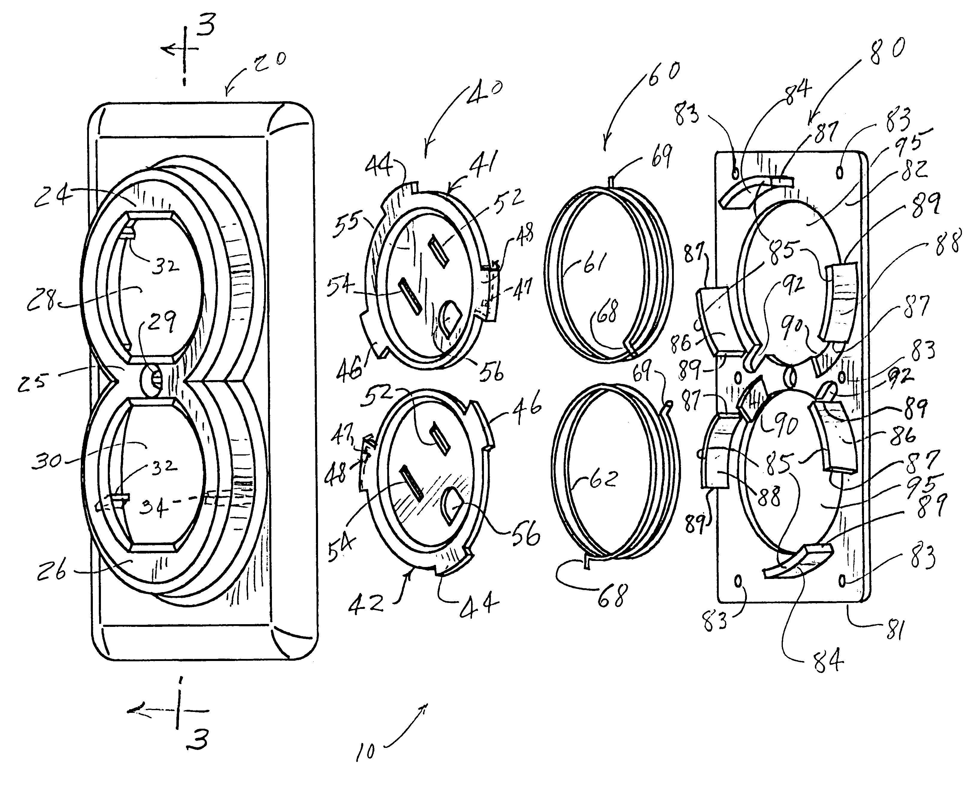
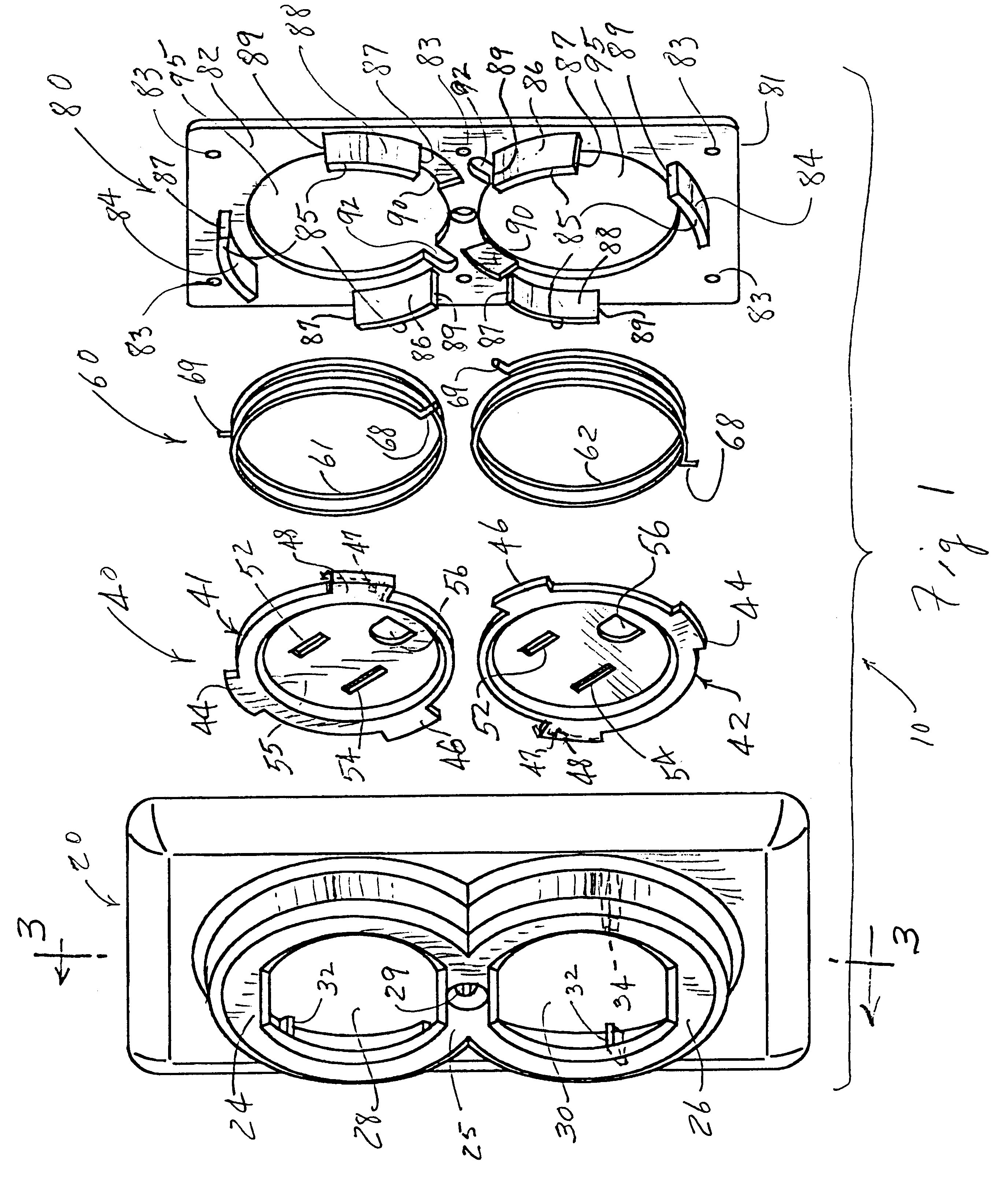
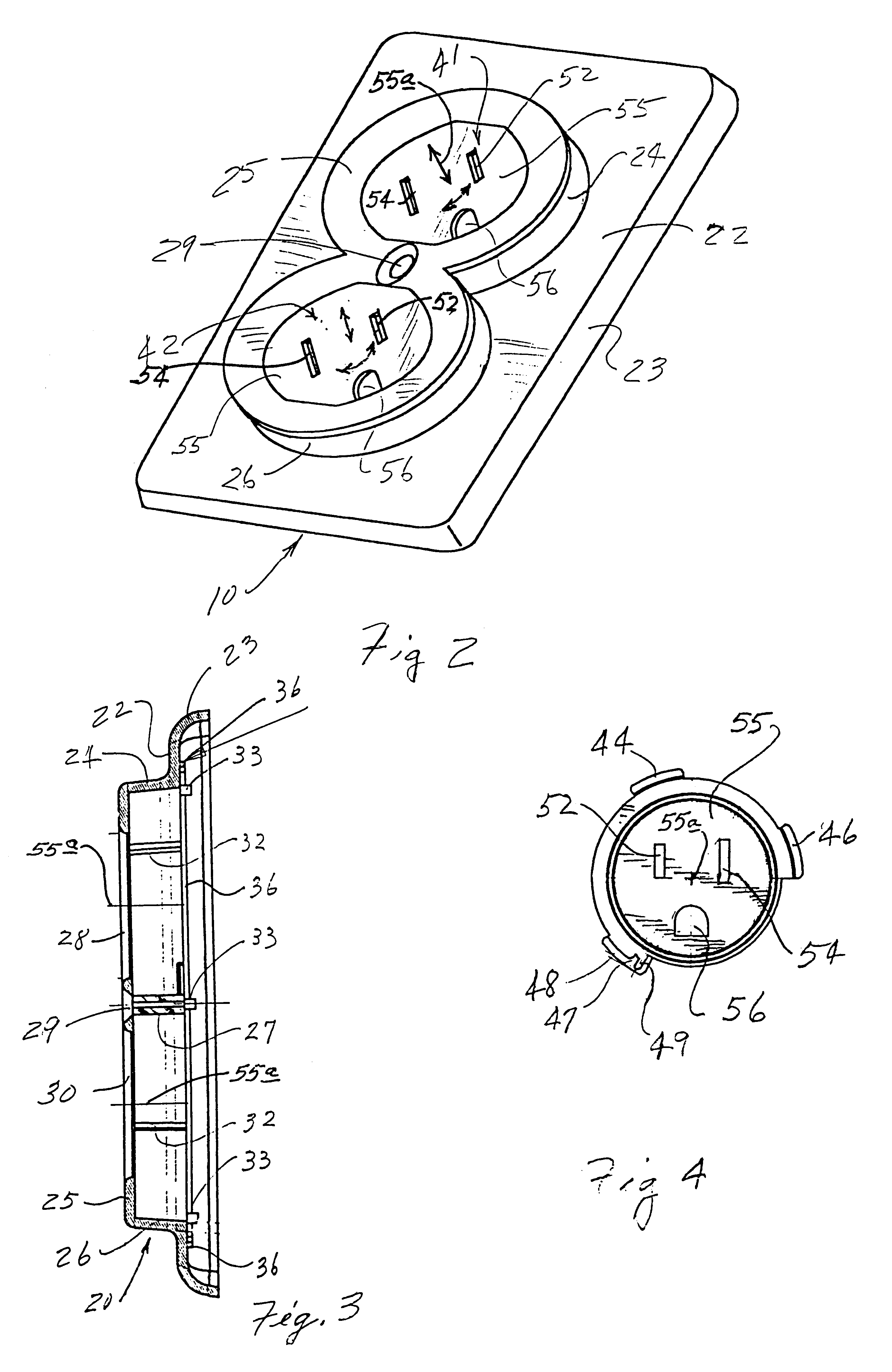
Referring to FIGS. 1 and 2 of the drawing, the numeral 10 generally designates an electrical outlet cover embodying the invention. The electrical outlet cover 10 generally comprises a cover plate 20, a floating socket cover assembly 40, a spring assembly 60 for exerting torque and compressional forces, and a back mounting plate 80.

Referring to FIGS. 1 and 3 of the drawing, cover plate 20 is preferably of unitary design and may be molded from a suitable plastic material. Cover plate 20 has a generally planar body portion 22 with curved flanges 23 extending around the outer periphery thereof. Cups 24 and 26 are formed on body portion 22 and have generally cylindrical outer walls which extend from body portion 22 and terminate with a generally planar face plate 25 having openings 28 and 30 extending therethrough. Cups 24 and 26 intersect at opposite sides of a common central wall 27 having a screw hole 29 formed therein.

A pair of ribs 32 and 34 extend inwardly from cylindrical walls of...


PUM


Abstract

An electrical outlet cover having a pair of floating socket covers which are resiliently urged toward a first position wherein holes in the floating socket covers are not aligned with holes in the electrical outlet. The floating socket cover must be rotated from the first position to a second position wherein holes in the socket cover are aligned with holes in the cover and then pushed toward the socket for moving prongs on the plug into holes in the socket. While prongs on the plug are moving into holes on the socket the prongs are covered by the floating socket covers to prevent electrical shock resulting from touching prongs of a plug that is partially plugged into the electrical socket.

Description

An electrical outlet cover having a cover plate which must be rotated for aligning prongs on a plug with holes in an outlet socket and then pushed inwardly for moving prongs on the plug into holes in the electrical outlet socket.BACKGROUND OF INVENTIONU.S. Pat. No. 5,944,542 discloses a device for shielding prongs on an electric plug as the plug is being pushed into or removed from an electrical outlet. The device includes a hollow housing, a face plate having holes for receiving prongs on an electric plug and a compression spring. The face plate is movably mounted within the housing, with the compression spring extending between the face plate and the housing such that the housing extends forward of the face plate and toward an electrical outlet when the adapter is mounted over the electrical outlet. As the prongs on the electrical plug are inserted into the socket in the electrical outlet, the housing extends around the prongs, covering the prongs. While this apparatus protects ag...

Claims


Application Information

Patent Timeline
Patent Type & Authority Patents(United States)
IPC IPC(8): H01R13/44H01R13/453
CPCH01R13/4532
Inventor LEE, HAN YOUNG
Owner LEE HAN YOUNG
Why Eureka
Try Eureka