Voltage equalizing apparatus and voltage equalizing method for battery devices

a voltage equalizing apparatus and battery technology, applied in the direction of charge equalisation circuit, transportation and packaging, arrangement of several simultaneous batteries, etc., can solve the problems of a larger apparatus and a higher cost, less utilization of the core, power loss and noise,

Inactive Publication Date: 2002-04-16
SUBARU CORP +1
View PDF3 Cites 79 Cited by
  • Summary
  • Abstract
  • Description
  • Claims
  • Application Information

AI Technical Summary

Problems solved by technology

There has been the following problems in such above-mentioned related art apparatuses for equalizing the voltages across each of a plurality of energy storage means (battery devices) interconnected in series by means of the switching of a converter.
Accordingly, the range of the change in magnetic flux density of the core is small, and hence the utilization of the core is less efficient.
The lower efficiency in core utilization implies the necessity of a larger cross section in the core for a specific output power, thereby causing the problems of a larger apparatus and a higher cost.
Further, the switching ON and OFF of the switching device for the voltage equalizing causes a problem that elec

Method used


Image

  • Voltage equalizing apparatus and voltage equalizing method for battery devices
  • Voltage equalizing apparatus and voltage equalizing method for battery devices
  • Voltage equalizing apparatus and voltage equalizing method for battery devices

Examples


first embodiment

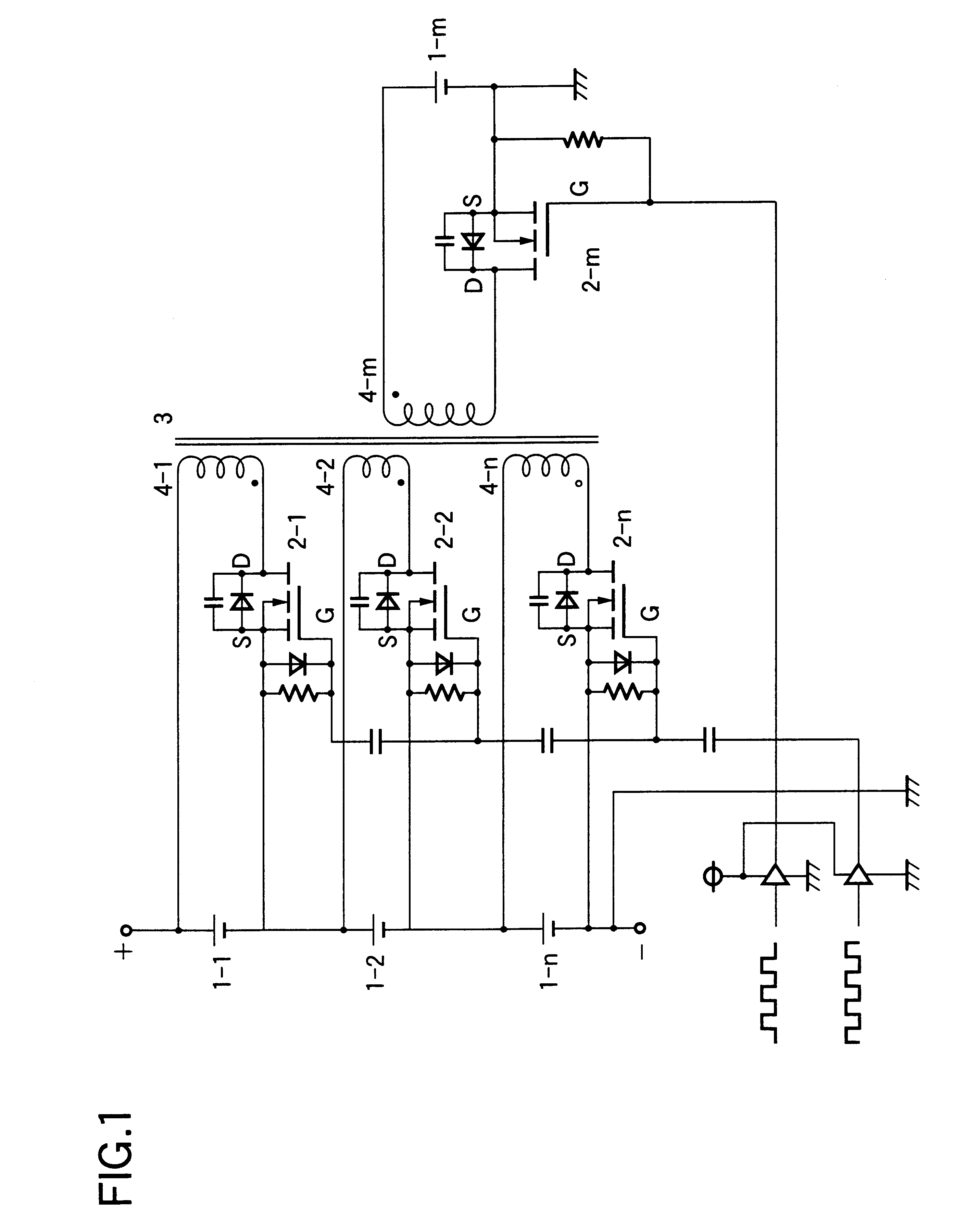
the present invention is described below with reference to FIG. 1.

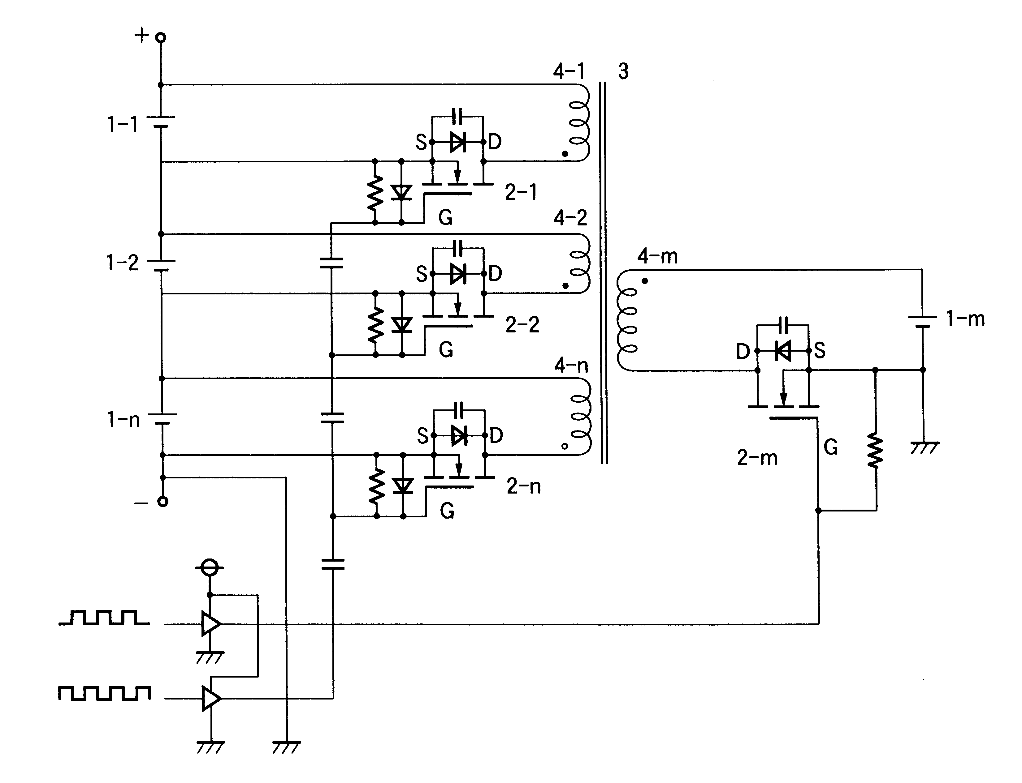
FIG. 1 shows a basic circuit of the present invention. Numerals 1-1 to 1-n designate a plurality of battery devices interconnected in series. Numerals 2-1 to 2-n designates a plurality of switching devices on a secondary side. Numeral 1-m is a battery device provided separately from the plurality of battery devices, and may be in combination with a direct-current power supply, a charger, or a generator. Numeral 2-m is a switching device on a primary side for conducting a current from the battery device 1-m to a primary winding 4-m wound on a common core of a transformer 3. The common core of the transformer 3 is further provided with a plurality of secondary windings 4-1 to 4-n for providing charging currents into the plurality of battery devices 1-1 to 1-n interconnected in series.

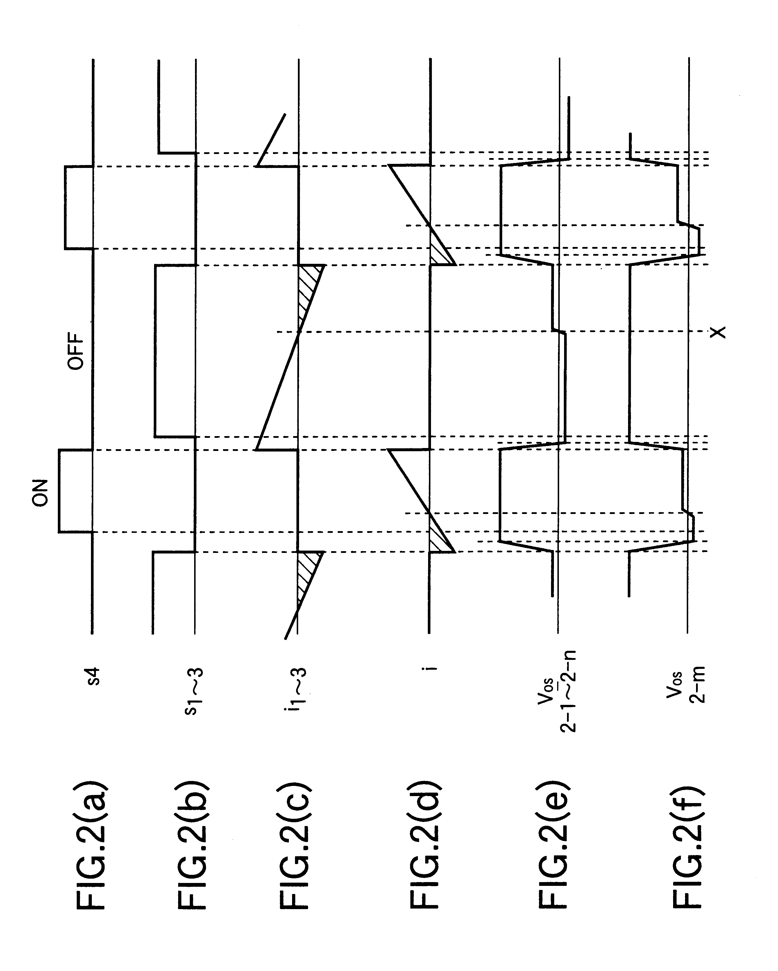
The switching device 2-m and the switching devices 2-1 to 2-n are provided with pulses in opposite polarity as shown in FIG. 1. Accordingl...

second embodiment

the present invention is described below with reference to FIG. 3.

In FIG. 3, the basic circuit of the present invention shown in FIG. 1 is treated as a single module. A plurality of such modules (three modules in FIG. 3) are provided, and a plurality of battery devices in respective modules are interconnected in series. However, a battery device 1-m and a pulse supplying circuit for switching ON and OFF each switching device are used in common.

Further, in FIG. 3, a module equalizing winding 4-m is common with an exciting winding from a battery device 1-m. However, the exciting winding and the module equalizing winding may be separate as shown in FIG. 4.

The operation of the second embodiment is basically the same as that of the first embodiment. However, voltage equalizing occurs also among the plurality of modules similarly to that within a single module, whereby overall voltage equalizing is achieved.

This configuration has a further effect that a required output voltage can be obta...


PUM


Abstract

In a voltage equalizing apparatus for battery devices, wherein each of a plurality of closed circuits is constituted of each of a plurality of battery devices interconnected in series on a secondary side, each of a plurality of secondary windings magnetically coupled with each other, and each of a plurality of switching devices on the secondary side, wherein a closed circuit is constituted of a battery device on a primary side, a primary winding magnetically coupled with the secondary windings in common, and a switching device on the primary side, and whereinthe plurality of switching devices on the secondary side and the switching device on the primary side are alternately switched ON and OFF, thereby equalizing the output voltages of the plurality of battery devices interconnected in series on the secondary side; the ON operation of the plurality of switching devices on the secondary side is continued until after the completion of release of exciting energy stored in a transformer.

Description

1. Field of the InventionThe present invention relates to an apparatus for performing energy transfer among a plurality of battery devices interconnected in series and carried on an electric car or a hybrid car and thereby equalizing each voltage across each of the plurality of battery devices interconnected in series.2. Description of the Related ArtThe related art in this field is disclosed, for example, in Japanese Laid-Open Patent Publication No. Hei 11-176483 and U.S. Pat. No. 5,003,244. In the configuration of the former patent as shown in FIG. 7, the output voltages E1 to En of a plurality of battery devices 1-1 to 1-n are interconnected in series. For the purpose of the balance correction of the output voltages of the plurality of battery devices, a switching transistor 2 connected to a primary coil Np in series is switched ON and OFF in response to the output voltages. A converter is composed of a plurality of secondary coils Ns each corresponding to each of the plurality o...

Claims


Application Information

Patent Timeline
IPC IPC(8): H02J7/00
CPCH02J7/0018
Inventor ANZAWA, SEIICHINISHIZAWA, HIROSHIMATSUI, FUJIO
Owner SUBARU CORP
Why Eureka
Try Eureka