Expandable mandrel having adjustable width

a mandrel and adjustable technology, applied in the field of rotating drums, can solve the problems of difficult control of the precise mating of the larger and smaller segments at the desired outer limit of travel, time-consuming and expensive, and cumbersome process, and achieve the effect of locking the drum width

Inactive Publication Date: 2002-05-21
DAVIAN ENTERPRISES LLC
View PDF5 Cites 48 Cited by
  • Summary
  • Abstract
  • Description
  • Claims
  • Application Information

AI Technical Summary

Benefits of technology

In the present drum, the axial and radial movements of the divided sets of segments are accomplished by unique mechanisms which provide for both selective and coordinated movements of the segments from locations external of the drum. These mechanisms include multiple lead screws which are disposed externally of the central main shaft of the drum and which are actuated simultaneously from a single location external of the drum to effect adjustment of the width of the drum, with disengagement of the lead screws from the external source of their adjustment once the width of the drum is selectively established, thereby ensuring "locking" of the drum width against unintended change thereof.

Problems solved by technology

This process is well known in the art to be cumbersome, time-consuming and expensive, and requires the keeping of an inventory of spacers.
Control over the precise mating of the larger and smaller segments at their desired outer limit of travel has proven to be difficult to control.
Accordingly, this mechanism represents an undesirable added cost in time and constitutes a point of potential need for ongoing adjustment over the useful life of a drum.

Method used


Image

  • Expandable mandrel having adjustable width
  • Expandable mandrel having adjustable width
  • Expandable mandrel having adjustable width

Examples


Embodiment Construction

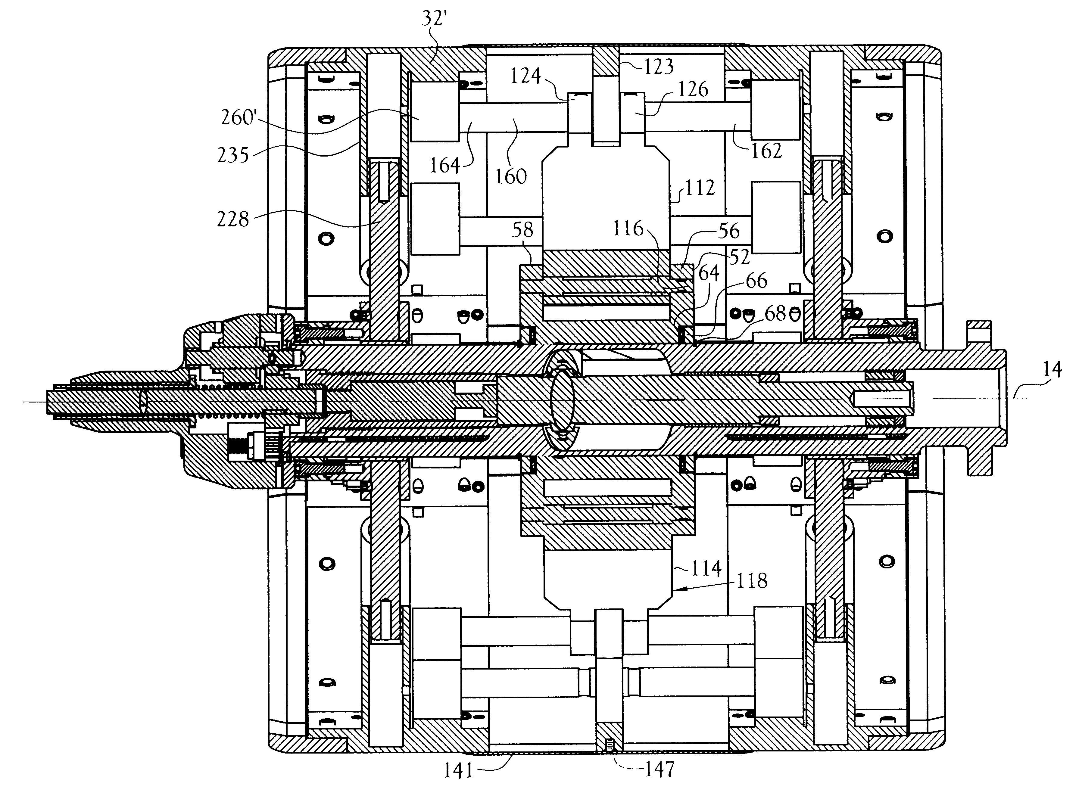
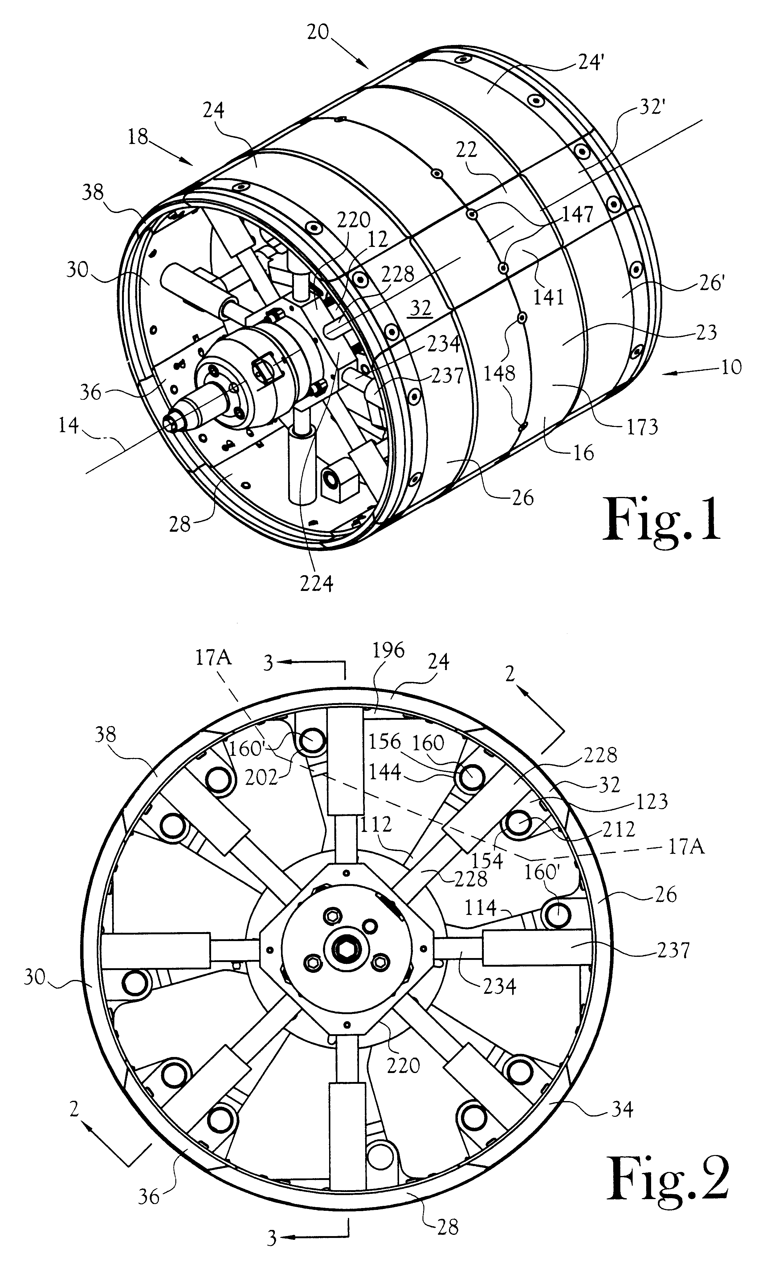
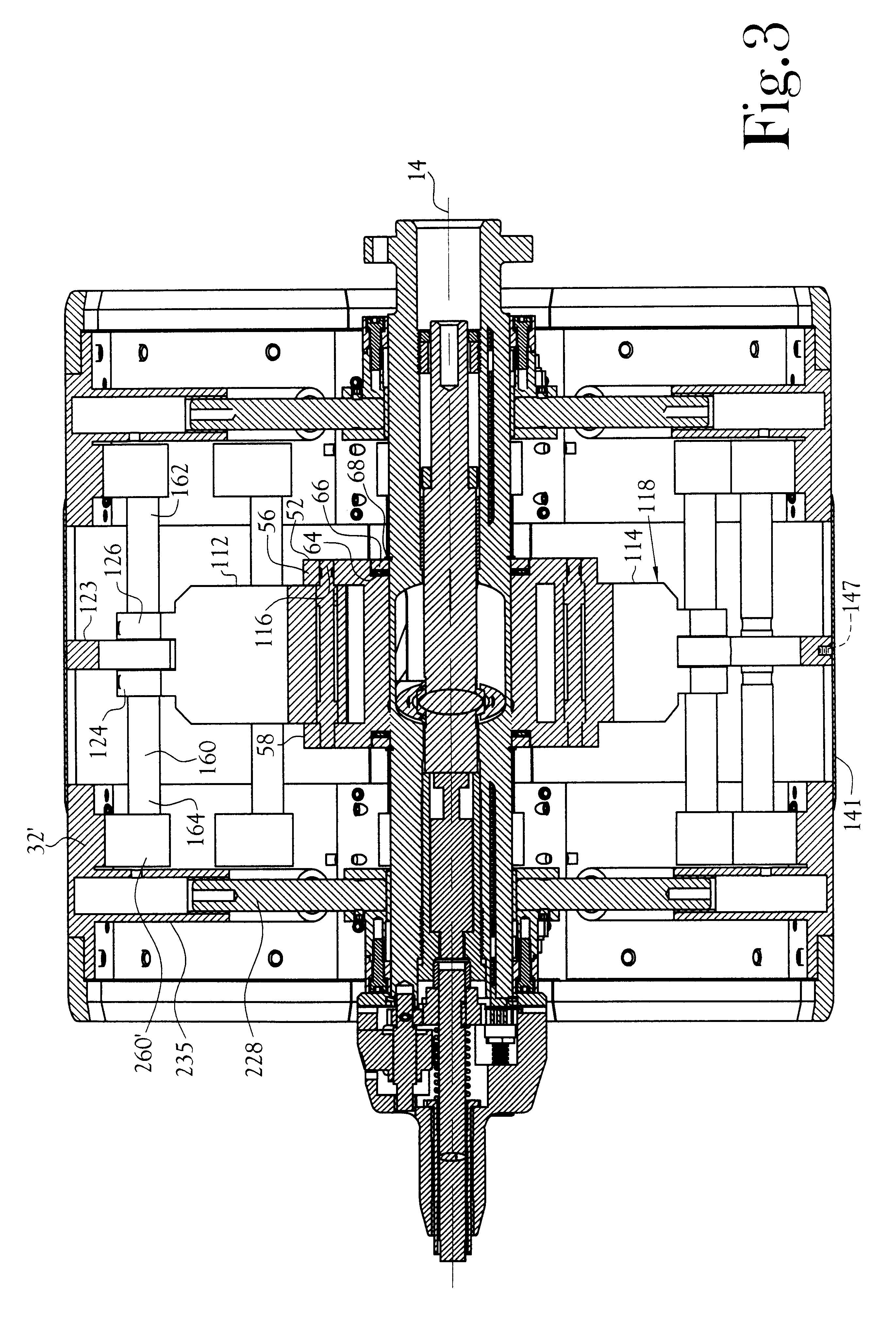
As depicted in FIGS. 1-5, a drum 10 in accordance with the present invention includes a main shaft 12 which extends through the width of the drum and defines the rotational axis 14 of the drum. The outer circumferential surface 16 of the drum is defined by first and second sets of segments, indicated generally by the numerals 18 and 20. In the depicted drum, each set of segments includes four large segments 24, 26, 28, and 30 (larger in width) and four small segments 32, 34, 36 and 38. The corresponding large and small segments of the second set of segments are identified by primed numerals. Within each set, the larger and smaller segments alternate in their position about the circumference of the drum. The first set 18 of the large and small segments is disposed outboard of the drum and the second set 20 is disposed inboard of the drum. These sets of segments are mounted for simultaneous axial movement toward and away from one another. The circumferential space between the sets of ...


PUM

PropertyMeasurementUnit
widthaaaaaaaaaa
rotationaaaaaaaaaa
widthsaaaaaaaaaa

Abstract

A rotatable drum useful in the manufacture of vehicle tires. A plurality of segments collectively define the outer circumferential surface of the drum. These segments are divided into two sets, one set being disposed on each of the opposite sides of a transverse center plane of the drum, the center plane being oriented normal to the rotational axis of the drum. The two sets of segments are mounted for selective positioning thereof axially of the drum from a location external of the drum to adjust the overall working width of the drum. Further, the segments are selectively positionable between expanded positions radially of the rotational axis of the drum to provide a relatively continuous circumferential outer surface of the drum for the layup of a tire carcass thereon, and collapsed positions radially of the drum to permit the removal of a formed toroidal carcass from the drum. Movement of the plurality of segments of each of the two sets of segments radially of the rotational axis of the drum is effected by "slaving" the two sets of segments off a central mechanism which controls the radial positions of all the segments simultaneously and equidistantly from the rotational axis of the drum, while further providing for axial movement of the two sets of segments relative to one another while the segments are positioned at any given radial location of the segments.

Description

This invention relates to tire building drums and particularly to a drum which is adjustable in width for use in the manufacture of tires of different widths employing the same drum.In the manufacture of vehicle tires, it is common practice to build up the tire carcass from individual components which are overlaid onto the outer circumference of a rotatable drum. Removal of the formed tire carcass from the drum requires collapse of the diameter of the drum to an extent sufficient to allow the toroidal carcass to be removed from the drum. U.S. Pat. No. 4,636,277 (the "277 patent") discloses a tire building drum of this type. This prior art drum is also representative of prior art drums wherein any change in the width of the drum requires physical exchange of spaces between the outer shell segments which define the outer circumference of the drum to that size required for the manufacture of a given tire width size. This process is well known in the art to be cumbersome, time-consuming...

Claims


Application Information

Patent Timeline
Patent Type & Authority Patents(United States)
IPC IPC(8): B29D30/24B29D30/20
CPCB29D30/24B29D2030/2657
Inventor ROBERTS, CLARK A.BYERLEY, MARK S.
Owner DAVIAN ENTERPRISES LLC
Why Eureka
Try Eureka