

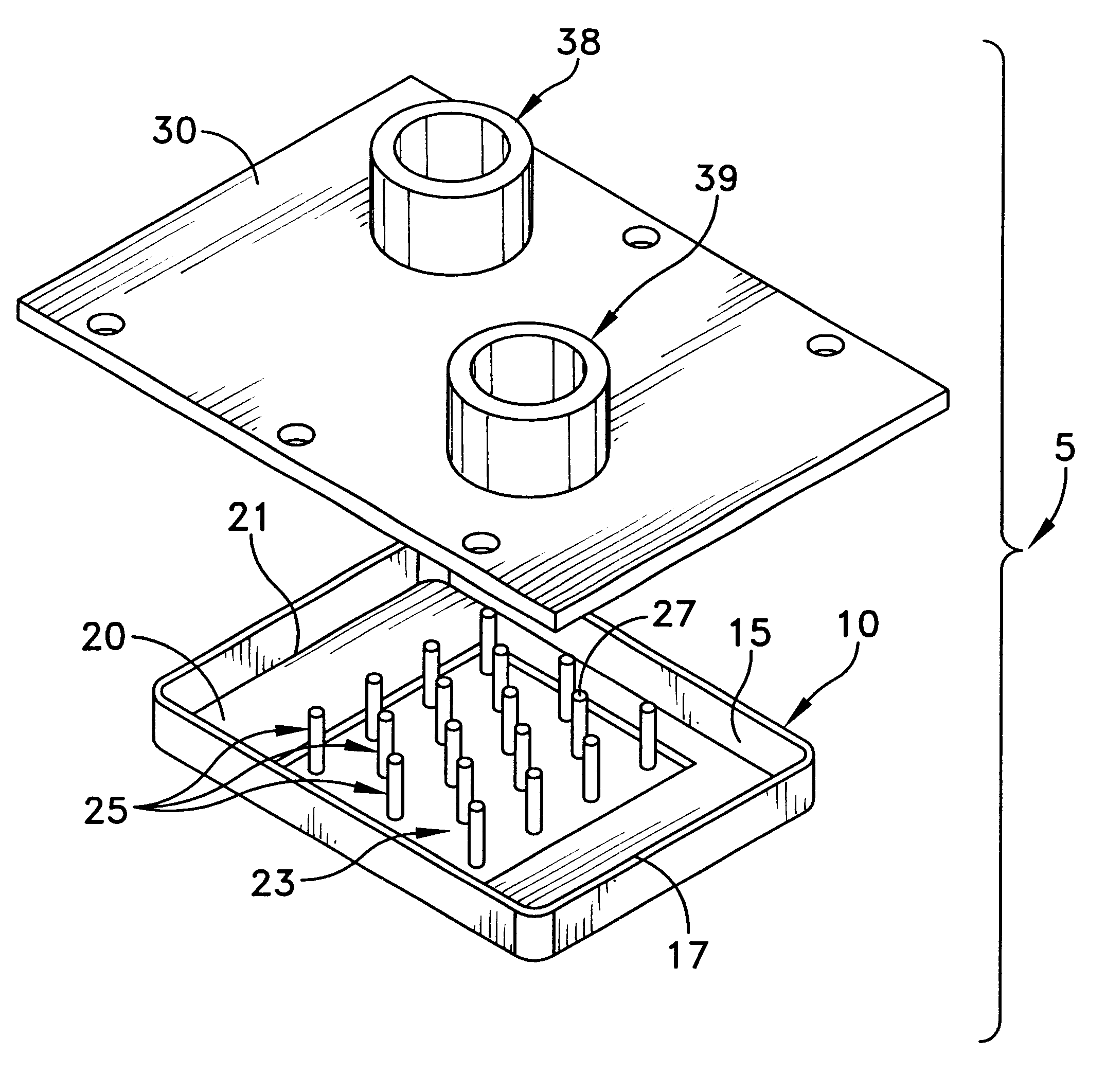
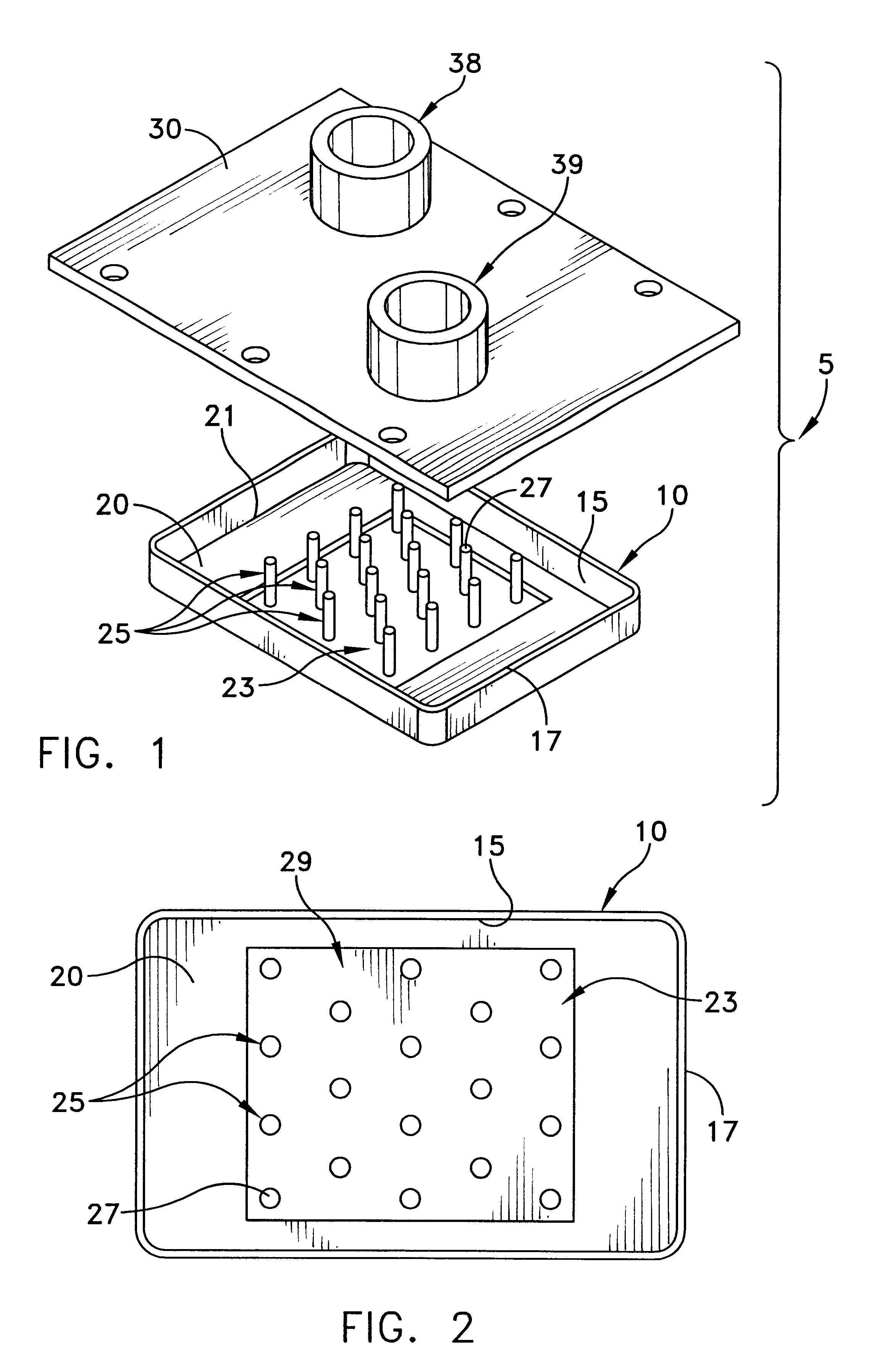
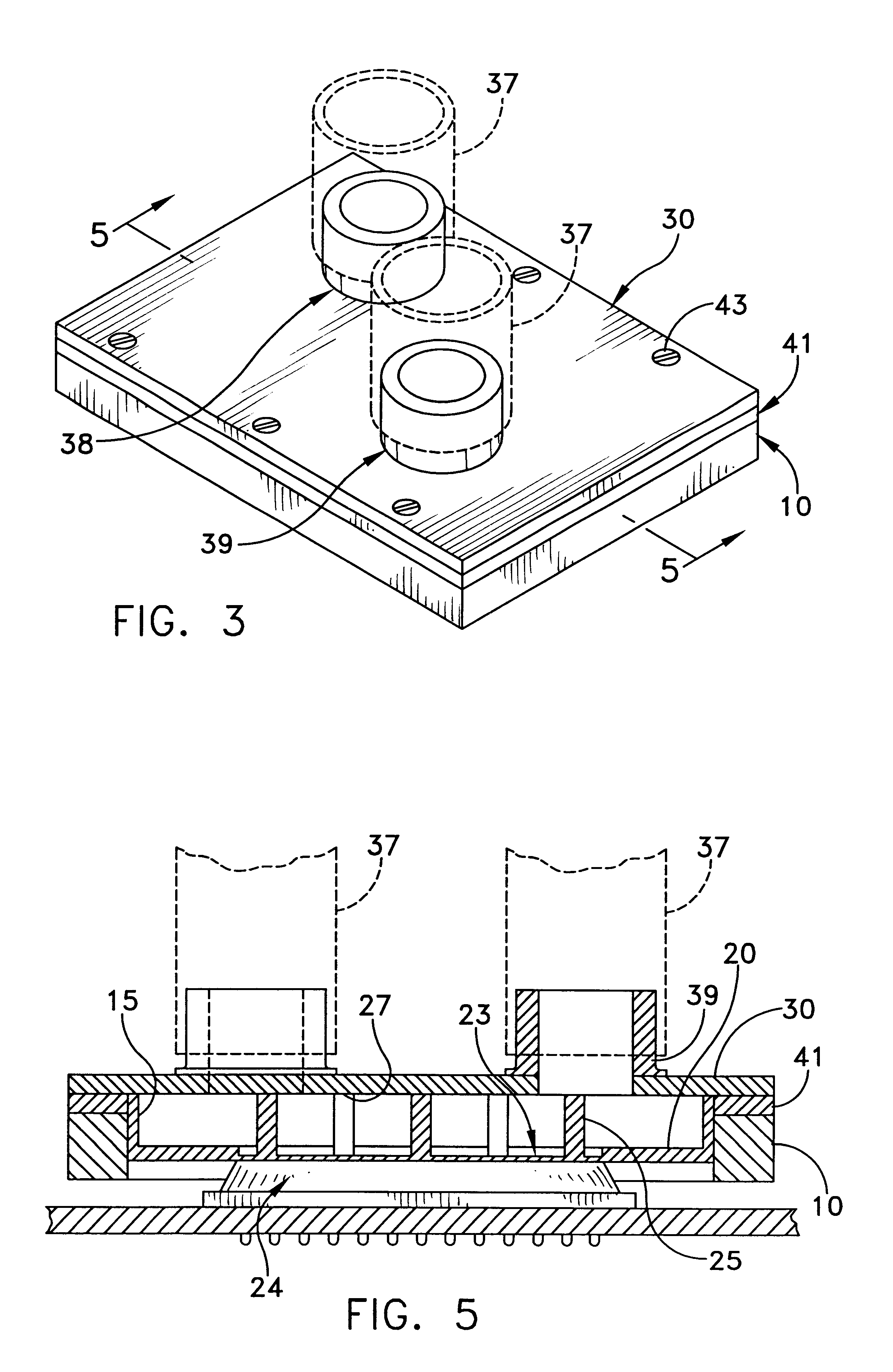
Liquid-cooled heat sink with thermal jacket
a heat sink and liquid-cooled technology, applied in the direction of corrosion prevention, semiconductor devices, lighting and heating apparatus, etc., can solve the problems of reducing the performance of semiconductor devices, requiring a considerable amount of power to operate, and reducing the performance of electronic circuits and their semiconductor devices, so as to reduce the rate of condensation of moisture, prevent deflection of the lid, and high liquid pressure
- Summary
- Abstract
- Description
- Claims
- Application Information
AI Technical Summary
Problems solved by technology
Method used
Image

Examples
Embodiment Construction
This description of preferred embodiments is intended to be read in connection with the accompanying drawings, which are to be considered part of the entire written description of this invention. In the description, relative terms such as "horizontal," "vertical," "up," "down," "top" and "bottom" as well as derivatives thereof (e.g., "horizontally," "downwardly," "upwardly," etc.) should be construed to refer to the orientation as then described or as shown in the drawing figure under discussion. These relative terms are for convenience of description and normally are not intended to require a particular orientation. Terms including "inwardly" versus "outwardly," "longitudinal" versus "lateral" and the like are to be interpreted relative to one another or relative to an axis of elongation, or an axis or center of rotation, as appropriate. Terms concerning attachments, coupling and the like, such as "connected" and "interconnected," refer to a relationship wherein structures are secu...
PUM
 Abstract
Description
Claims
Application Information