Jewelry enhancing lighting device and process

a lighting device and jewelry technology, applied in lighting and heating equipment, instruments, containers, etc., can solve problems such as stress failure, work hardening wires, and inability to provide jewelry display boxes

Inactive Publication Date: 2002-06-18
GAGLIARDI FR S
View PDF8 Cites 65 Cited by
  • Summary
  • Abstract
  • Description
  • Claims
  • Application Information

AI Technical Summary

Benefits of technology

It is yet another object of the present invention to provide a jewelry display device which is capable of under lighting multiple pieces of jewelry simultaneously.

Problems solved by technology

The above patents to not provide for a jewelry display box with features that actively enhance the displayed jewelry.
Constant opening of the box will flex the electrically conductive wires connecting the power source to the lamp, thereby work hardening the wire and leading to stress failure.
Frequently, this light shines into the eyes of a viewer and detracts from the beauty of the displayed article.
This design also does not allow for easy removal of the rings for use or inspection by an individual.
Furthermore, the use of alternating current electricity with this device limits its use to jewelers or collectors.
While these patents provide a variety of different active lighting schemes, they do not address problems inherent in lighting jewelry with a weak light source located far away from the displayed jewelry.
First, the weak nature of the light source provides that there will only be minimal additional lighting provided under normal viewing conditions unless a high wattage lamp is used thereby shortening the battery lifetime.
Second, by top lighting jewelry, shadows are created that tend to obscure many of the ornamental and desirable features intended to be displayed by the light box.
Third, top lighting frequently places the light source in direct view of the observer, thus causing a glare that detracts from the beauty inherent in ornamental jewelry.
None of the prior art provides for an increased intensity lighting source located in the bottom section near the jewelry, nor for the combination of light and sound to enhance the display of jewelry.

Method used


Image

  • Jewelry enhancing lighting device and process
  • Jewelry enhancing lighting device and process
  • Jewelry enhancing lighting device and process

Examples


first embodiment

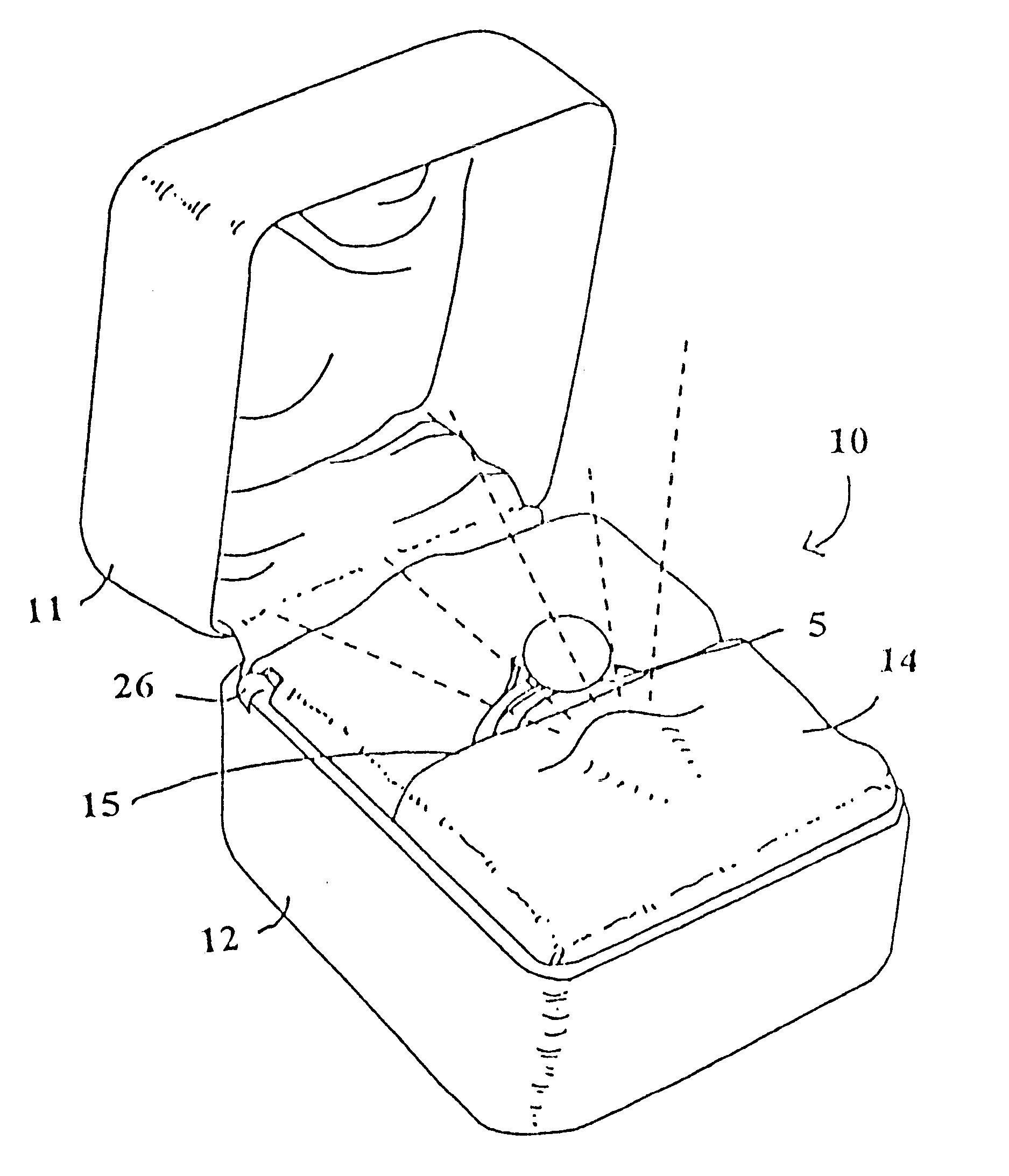
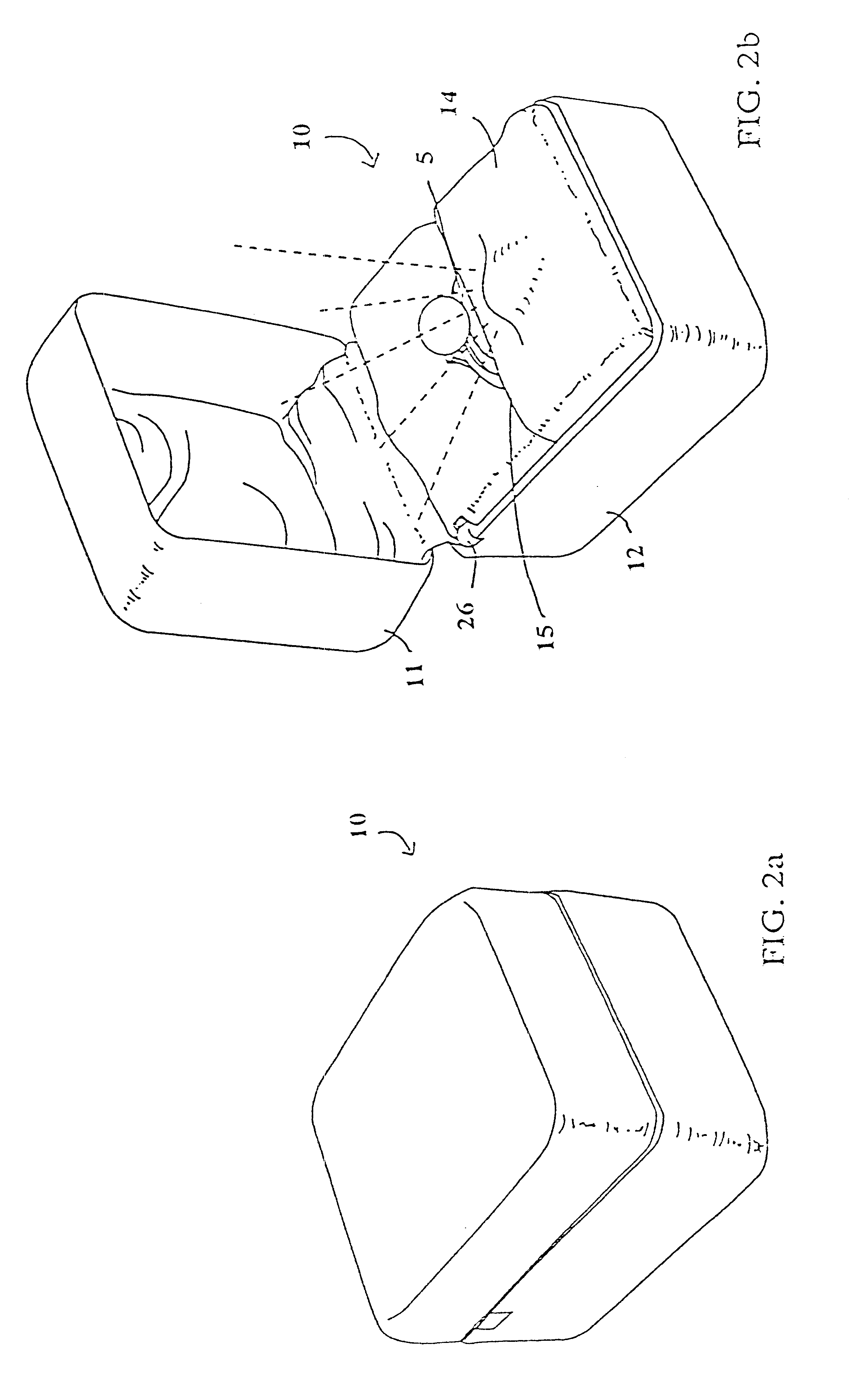
In a first embodiment, the electrical circuit 20 comprises at least a power source 21, such as a battery, a light source 30, such as a light bulb connected to the battery, and a switch 22 connected to the power source 21 and the light source 30. The electrical circuit 20 is preferably hidden from view by the display insert 14.

The action of the switch 22 is coupled to opening the jewelry box 10 such that when the jewelry box 10 is opened, the electrical circuit 20 is completed, and the light source 30 is illuminated, thus under lighting the displayed piece of jewelry.

In the first preferred embodiment, the switch 22 preferred is a spring biased switch with a plunger 25 and a lever 26 engaging the plunger 25. The lever 26 projects over a top edge 27 of the bottom section 12, preferably near the hinge 13. As the top section 11 of the jewelry box 10 is opened, the plunger 25 is allowed to move upward under the influence of the spring biasing thereby completing the circuit 20; thus energi...

second embodiment

the present invention utilizes a switch 22 that comprises a pair of contact surfaces 24 located near the hinge 13, shown in FIG. 5a and FIG. 5b. When the jewelry box 10 is in a closed configuration the pair of contact surfaces 24 are not in physical contact thereby preventing the flow of electricity, but upon opening the jewelry box 10, the pair of contact surfaces 24 come into contact, thereby completing the electrical circuit 20. It is contemplated that the hinge 13 may act as one of the pair of contract surfaces.

The light source 30 of the present invention is a small light bulb, but may be any number of electrically powered light generating devices, and is positioned within the illumination aperture 16 in the display insert 14. The illumination aperture 16 is located near the jewelry holder 15 of the display insert 14 and directs radiated light toward the jewelry 5 contained within the jewelry box 10. Furthermore, it is preferable that the light source 30 is placed in a positione...

third embodiment

In the present invention, a music source 40 is placed in series within the electrical circuit 20. An example of this circuit is illustrated in FIG. 3. The music source 40 may be a preprogrammed integrated chip which inherently emits music, or it may be a separate, frequency generating electrical circuit coupled to a small speaker for sound generation. Thus, when the electrical circuit 20 is completed, the light source 30 illuminates the displayed jewelry and a pleasant musical tune is played.


PUM


Abstract

A display box for aesthetically presenting jewelry is provided. The display box of the present invention includes provisions for under lighting the displayed jewelry when the display box is opened. Additionally, the display box of the present invention may include a sound source or voice recordable chip connected in series with the light source, thus providing visual and aural enhancement of the displayed jewelry. The display box of the present invention may additionally be adapted to hold, display and illuminate more than one piece of jewelry.

Description

The present invention relates generally to jewelry and more particularly concerns jewelry display boxes wherein unique electrical lighting and sound features enhance the display box's utility. The invention will be specifically disclosed in connection with a jewelry display box which, when opened, under lights the displayed piece of jewelry. Additionally, the jewelry display box may include sound emitting devices which provide pleasing music and / or messages. These display boxes provide a more aesthetically pleasing manner in which to display jewelry.Jewelry has become an important part of the world economy. A significant fraction of a person's disposable income may be devoted to the purchase of jewelry to display affection, devotion or gratitude to another. As a result of this purchasing power and activity, a highly competitive jewelry market has evolved. Since every jeweler provides similar jewelry, a jeweler who provides his or her goods in the most aesthetically appealing manner,...

Claims


Application Information

Patent Timeline
Patent Type & Authority Patents(United States)
IPC IPC(8): A47F7/03A47F7/02F21V33/00F21V23/04A45C11/16A45C15/06
CPCA45C11/16A45C15/06F21V33/0004F21V23/04A47F7/03
Inventor GAGLIARDI, FRANK S.
Owner GAGLIARDI FR S
Why Eureka
Try Eureka