Plate suitable as a noise protection wall

a technology for noise protection and plates, applied in the direction of walls, instruments, flooring, etc., can solve the problems of increasing the production cost of such plates, unproblematic cleaning of plates, and determining whether the test methods used to substantiate this alleged effect are sufficien

Inactive Publication Date: 2002-07-02
ROHM GMBH
View PDF10 Cites 15 Cited by
  • Summary
  • Abstract
  • Description
  • Claims
  • Application Information

AI Technical Summary

Problems solved by technology

The cleaning of the plate is unproblematic.
Nevertheless, it must be stressed that the central location substantially increases the production cost of such plates.
However, it remains to be determined whether the test methods utilized to substantiate this alleged effect are sufficient, since the utilized impact energies lie in an insufficiently high area.

Method used


Image

  • Plate suitable as a noise protection wall
  • Plate suitable as a noise protection wall
  • Plate suitable as a noise protection wall

Examples


example 1

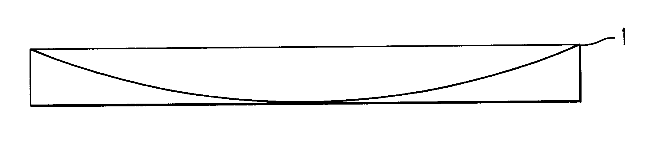
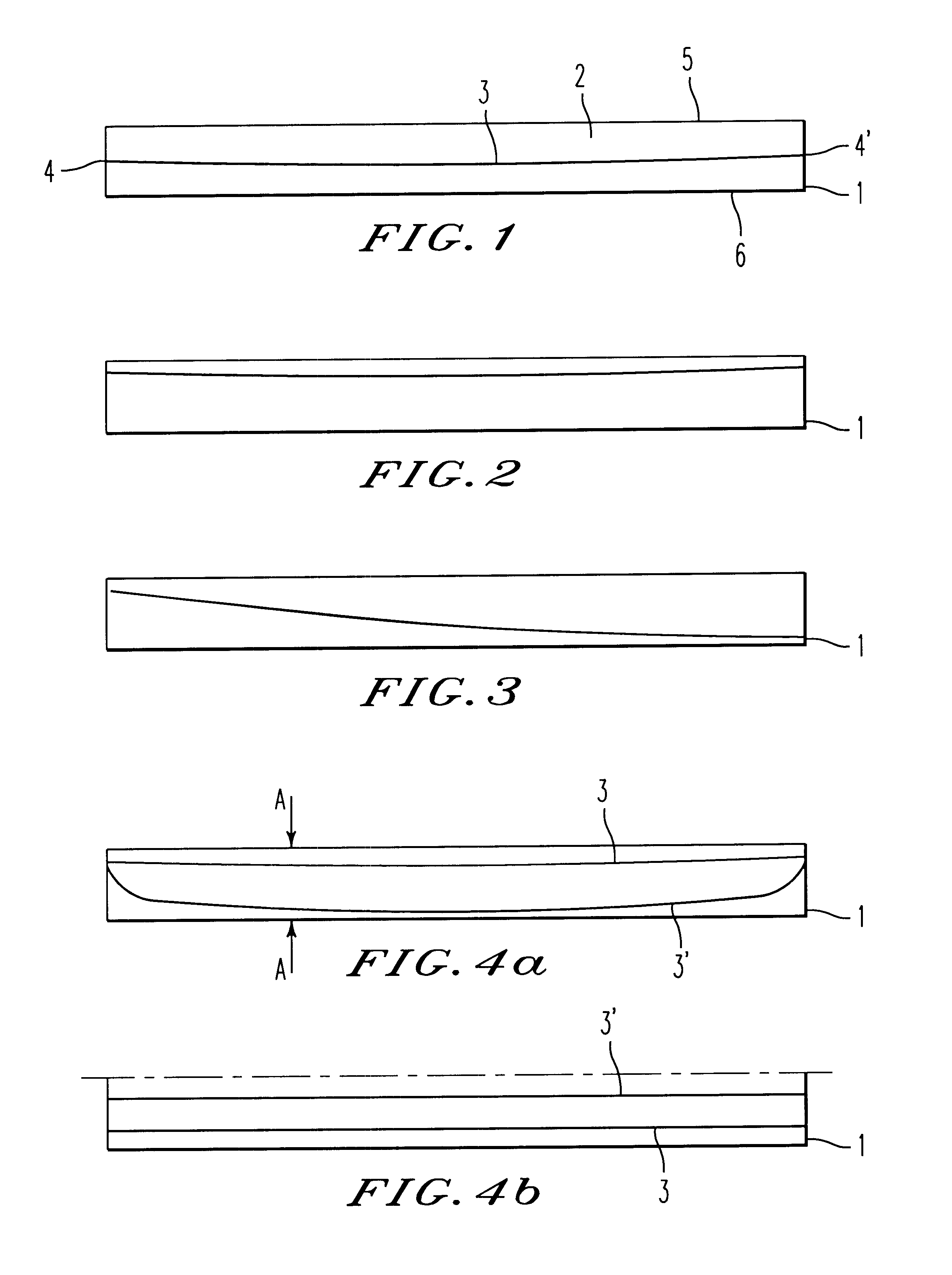
In order to produce an acrylic, glass plate in accordance with FIG. 1 a chamber is formed out of two polished silicate glass plates of dimension 2 meters by 3 meters separated by a space of 20 mm. Into this Chamber with a separation of 30 mm there were provided parallel to each other monofilpolyamide threads having a diameter of 2 mm. These polyamide threads were so provided that they each had a sag of 2 mm. Thereafter, the chamber was filled with methylmethacrylate syrup which contained a radial forming initiator and capped. The filled chamber was placed in a water bath and by means of warming the syrup was cross-linked to a high molecular polymethylmethacrylate. The chamber was polymerized lying down so that the sagging of the threads was perpendicular to the main plane of the polymethylmethacrylate. After removal of the forms there was given a cast acrylic glass plate 2 meters by 3 meters in size and 20 mm thick with embedded polyamide threads. The positioning of polyamide thread...

example 2

For the formation of a system element:

In accordance with FIG. 2 a chamber of 20 mm thickness was built in a Rostero oven. Into this chamber polyamide cords separated by 30 mm were laid which were parallel to the surface and had a deviation of 5 mm. The diameter of the polyamide strings utilized was 2 mm. The thus obtained chamber was filled with methylmethacrylate syrup containing a radical forming initiator. After filling the chamber was evacuated and heated to 50.degree. C. to start the polymerization. Because of the vertical orientation of the polymerization chamber the polyamide strings hung parallel to the surface.

After complete hardening of the plate this was removed from the form and subjected to the breaking test. Whether carried out at -20.degree. C. or +20.degree. C. no free fragments were noted.

example 3

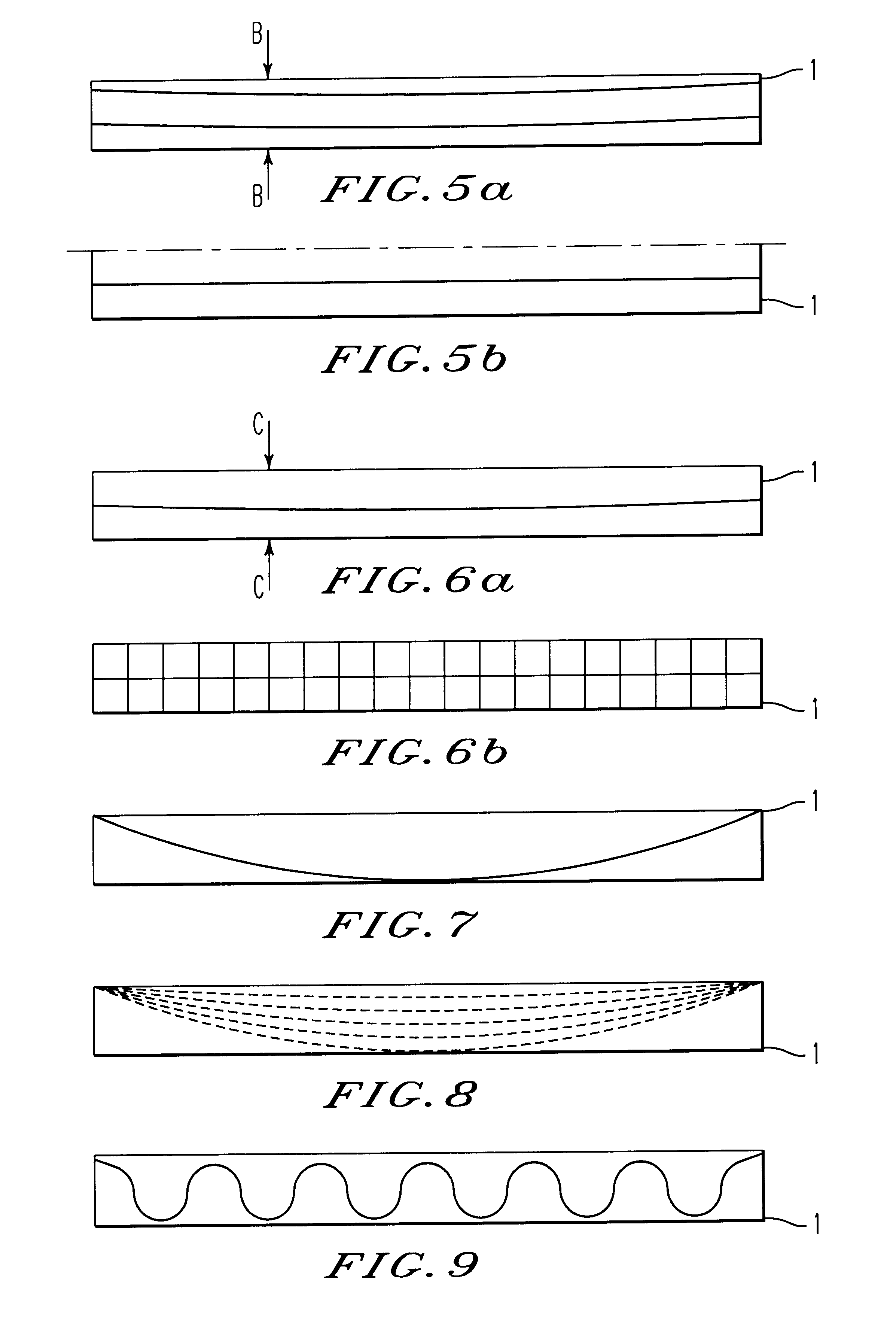
The procedure was carried out in accordance with Example 1 with the difference that in place of monofilament polyamide threads a polyamide grid of monofilament threads having a diameter of 2 mm and a stitch width of 50 .times.50 mm were installed with a maximum sag of 8 mm. These plates had a thickness of 20 mm and were subjected to the pendulum test. The difference was that the plate was not built up three-sided by only single-sided. In the pendulum test carried out at 20.degree. C. there were no free broken pieces.


PUM


Abstract

A plate utilizable in a noise protection wall of fragile acrylic glass comprising a plurality of side by side synthetic monofilament plastic threads for embedded in and running along the plate for splinter binding on breakage of the glass wherein, at least one thread has a maximum deviation of 1 mm or more from a theoretical straight line connecting the ends of said thread.

Description

Plates suitable as noise protection elements made of basically frangible acrylic glass in which plastic monofilament threads are embedded to reduce splintering in the possible event of breakage of the glass.DISCUSSION OF THE PRIOR ARTPlates of the prior art which are secured against the origination and falling down of loose fragments are known from EP 0 407 852. The plates disclosed therein contain, embedded therein, relative to the plate cross-section substantially essentially centrally located monofilament synthetic threads, or a web of such threads. Monofilament threads made of polyamide are particularly suitable as synthetic threads. In the above-mentioned EP 0 407 852 it is emphasized that the embedded synthetic threads are substantially invisible, so that the elements remain transparent. Furthermore, because the synthetic threads are embedded into the interior of the plate an optimal protection against weathering is provided. The cleaning of the plate is unproblematic. Further...

Claims


Application Information

Patent Timeline
Patent Type & Authority Patents(United States)
IPC IPC(8): E01F8/00G10K11/162G10K11/18G10K11/22
CPCE01F8/0017E01F8/0023
Inventor SCHOLA, EGBERTSEELMANN, PETERMOLNAR, GERALD
Owner ROHM GMBH
Why Eureka
Try Eureka