Hydraulically-actuated fuel injector having front end rate shaping capabilities and fuel injection system using same

a fuel injector and hydraulic actuator technology, applied in the direction of fuel injection apparatus, spraying apparatus, charge feed system, etc., can solve the problem of not being able to produce some front end rate shapes

Inactive Publication Date: 2002-07-02
CATERPILLAR INC
View PDF16 Cites 11 Cited by
  • Summary
  • Abstract
  • Description
  • Claims
  • Application Information

AI Technical Summary

Benefits of technology

FIG. 6 is a graph of injection rate versus time for a fuel injector having a relatively small diameter spill passage and a fuel injector having a relatively large diameter spill passage.
FIG. 7 is a graph of injection rate versus tim...

Problems solved by technology

While a number of fuel injectors have been developed that have limited rate shapin...

Method used


Image

  • Hydraulically-actuated fuel injector having front end rate shaping capabilities and fuel injection system using same
  • Hydraulically-actuated fuel injector having front end rate shaping capabilities and fuel injection system using same
  • Hydraulically-actuated fuel injector having front end rate shaping capabilities and fuel injection system using same

Examples


Embodiment Construction

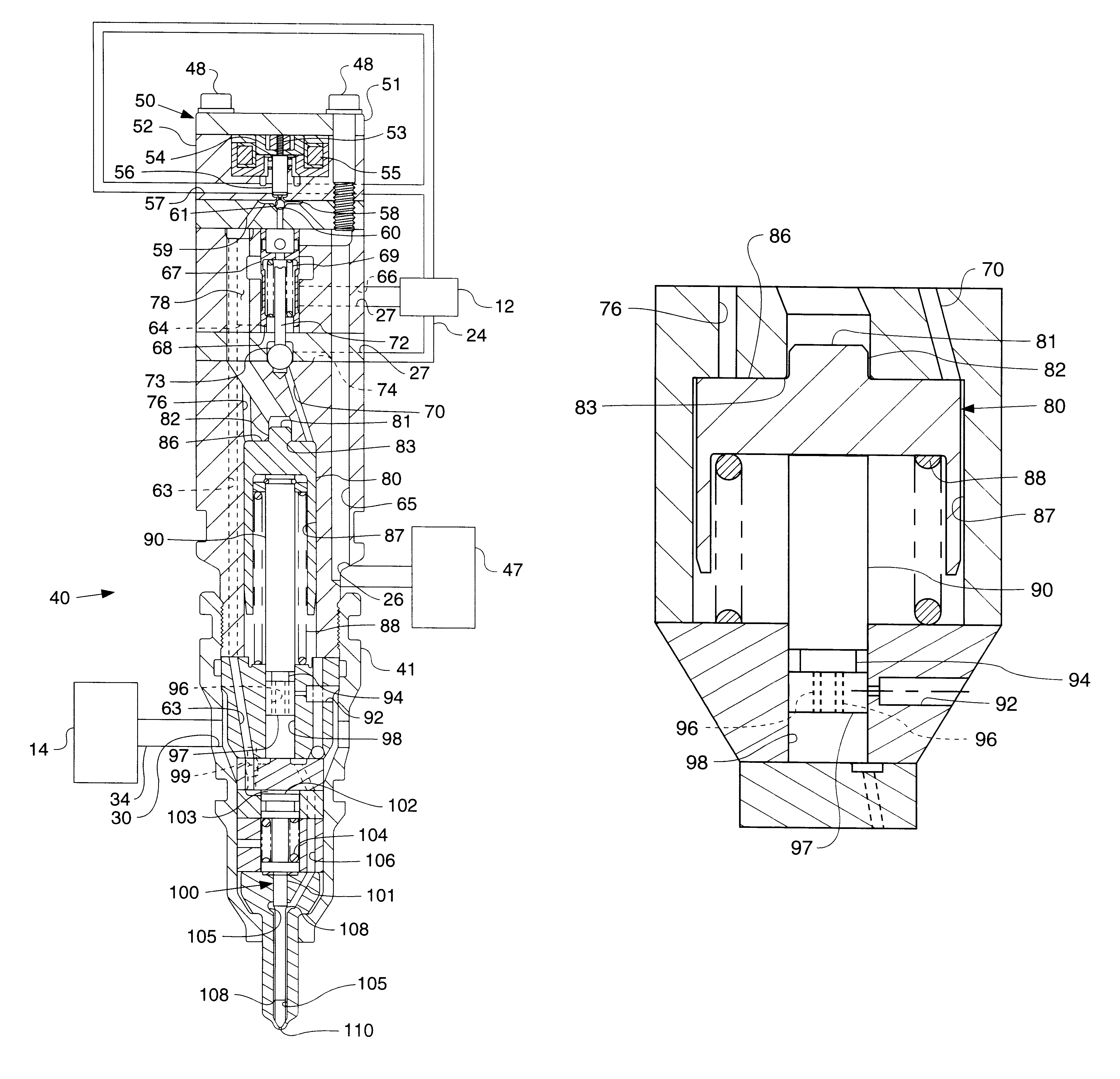
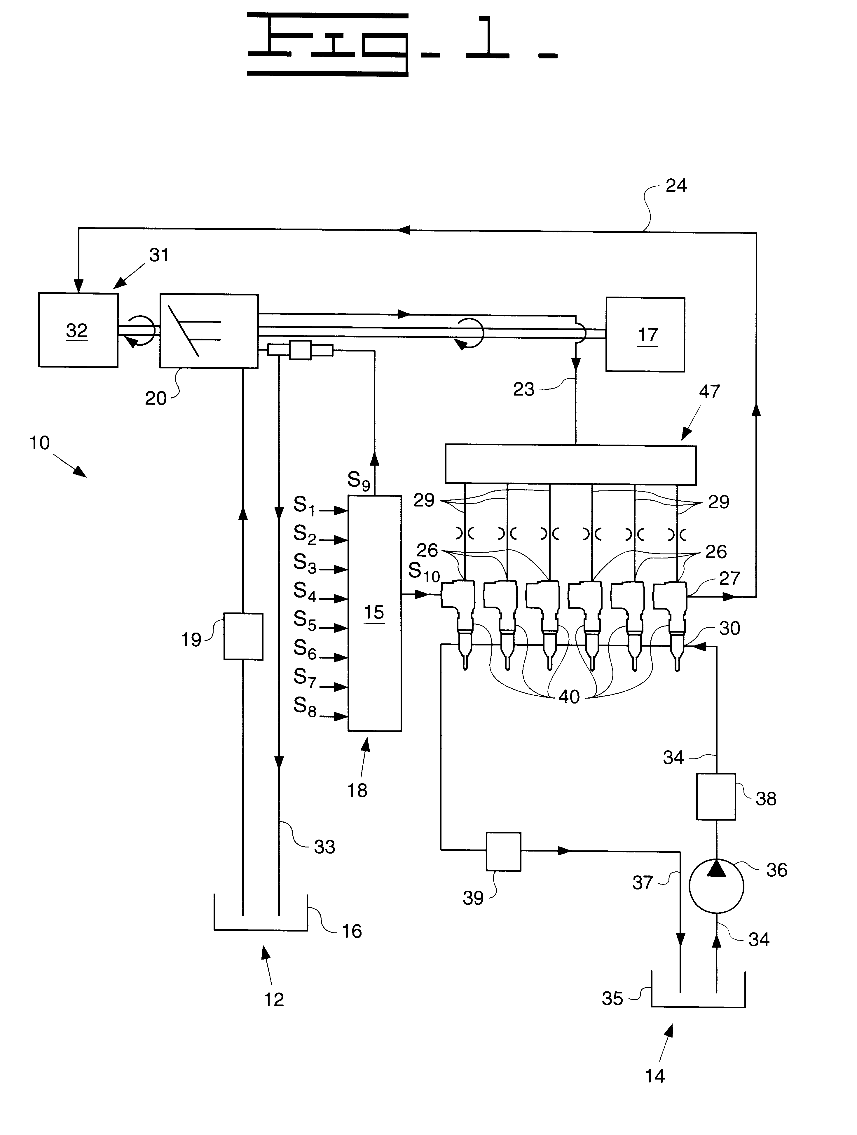
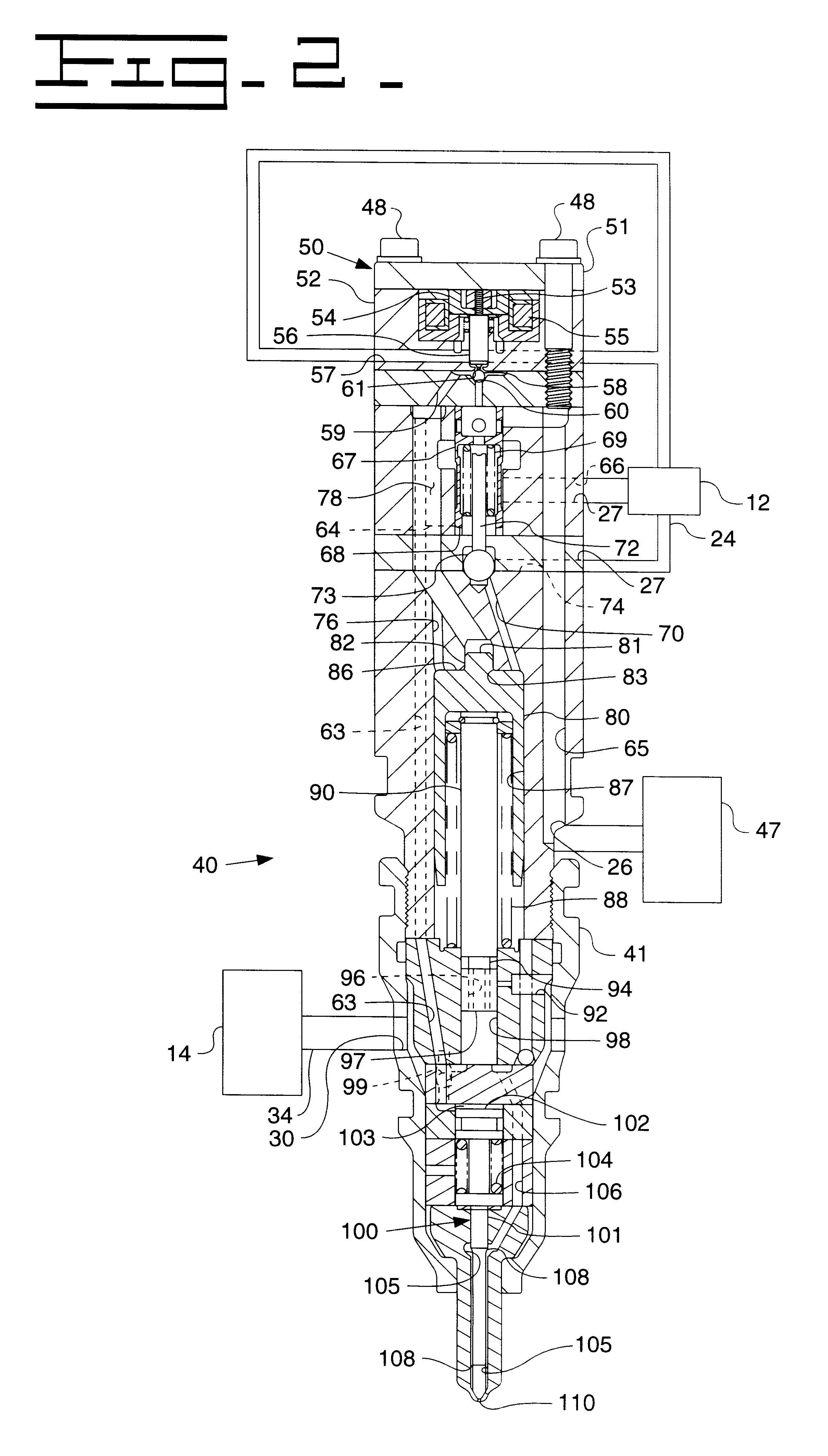
Referring now to FIG. 1 there is shown a hydraulically-actuated fuel injection system 10 according to the present invention. Fuel injection system 10 includes at least one hydraulically actuated fuel injector 40, all of which are adapted to be positioned in a respective cylinder head bore of an engine. Fuel injection system 10 includes a source of low pressure actuation fluid 12 for supplying actuation fluid to each fuel injector 40 at a device inlet 26, and a source of fuel 14 for supplying fuel to each fuel injector 40 at a fuel inlet 30. Fuel injection system 10 also includes a means for recirculating actuation fluid 31, containing a hydraulic motor 32, which is capable of recovering hydraulic energy from oil exiting fuel injectors 40. A computer 18 is also included in fuel injection system 10 to control timing and duration of injection events. Computer 18 includes an electronic control module 15 which controls the timing and duration of injection events and pressure in a high pr...


PUM


Abstract

A hydraulically actuated fuel injection system according to the present invention comprises at least one hydraulically actuated fuel injector that includes an injector body that defines a fuel pressurization chamber. A pumping element having a stepped top is movably mounted in a pumping bore defined by the injector body, wherein the pumping element defines at least one internal passageway. The pumping element is movable a distance between a first position and a second position. A spill passage defined by the injector body is open to the fuel pressurization chamber via the at least one internal passageway over a portion of the distance.

Description

The present invention relates generally to fuel injector rate shaping, and more particularly to front end rate shaping an injection event of a hydraulically actuated fuel injector utilizing a spill passage and a stepped pumping element.1. Background ArtIt has long been known in the art that injector performance can be increased, and undesirable emissions reduced, by controlling the mass flow rate of fuel injected into a combustion chamber during an injection event. It is also believed that the ability to front end rate shape an injection event can further reduce emissions and noise level while increasing injector performance. While a number of fuel injectors have been developed that have limited rate shaping capabilities, the ability to produce some front end rate shapes has not been possible. Therefore, a fuel injector having a broader range of front end rate shaping capabilities would allow engineers to further reduce undesirable emissions while increasing fuel injector performanc...

Claims


Application Information

Patent Timeline
IPC IPC(8): F02M57/00F02M57/02F02M45/06F02M45/00
CPCF02M45/066F02M57/025
Inventor DESAI, CHETAN J.NAN, XINSHUANG
Owner CATERPILLAR INC
Why Eureka
Try Eureka