Secondary Battery System

a battery system and secondary battery technology, applied in batteries, hybrid vehicles, instruments, etc., can solve the problem of increasing the error of the so

Active Publication Date: 2016-12-01
HITACHI ASTEMO LTD
View PDF7 Cites 22 Cited by
  • Summary
  • Abstract
  • Description
  • Claims
  • Application Information

AI Technical Summary

Benefits of technology

[0010]According to the secondary battery system of the present invention, a large amount of time is not required in investigating the battery characteristics. An accurate SOC can thus be calculated in a simple manner.

Problems solved by technology

This method integrates a measurement error included in the measured current value as well, and thus has a problem that an SOC error increases as time elapses.

Method used


Image

  • Secondary Battery System
  • Secondary Battery System
  • Secondary Battery System

Examples


first embodiment

[0025]In a first embodiment, there will be described a case where the present invention is applied to a secondary battery system that is mounted in a vehicle system included in a hybrid vehicle (HEV), a plug-in hybrid vehicle (PHEV) and an electric vehicle (EV).

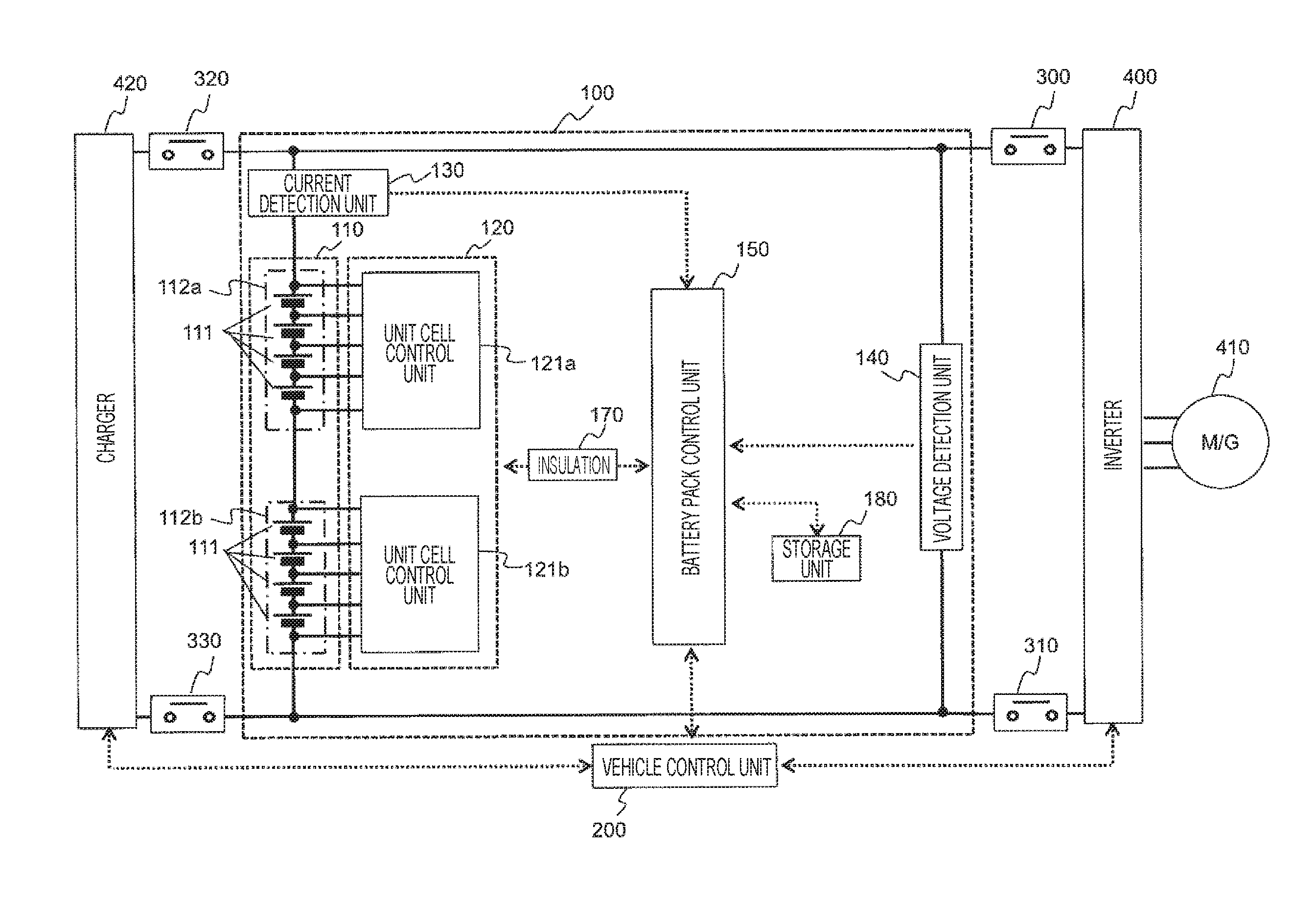
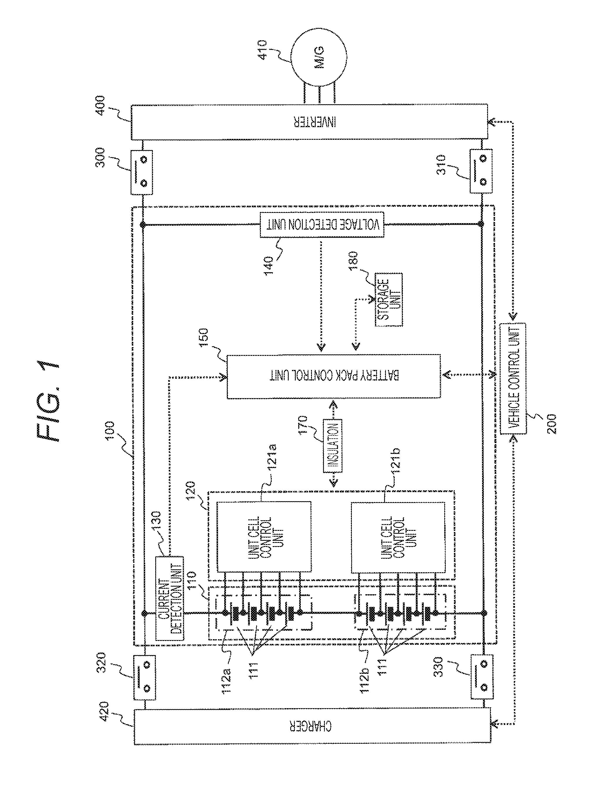
[0026]FIG. 1 is a diagram illustrating the configuration of a secondary battery system 100 and its periphery according to the first embodiment. The secondary battery system 100 is connected to an inverter 400 performing PWM control on a motor / generator 410 via relays 300 and 310. The secondary battery system 100 is also connected to a charger 420 via relays 320 and 330. A vehicle control unit 200 communicates with a battery pack control unit 150, the charger 420 and the inverter 400.

[0027]The secondary battery system 100 includes a battery pack 110, a unit cell management unit 120, a current detection unit 130, a voltage detection unit 140, the battery pack control unit 150, a storage unit 180, and an insulating element 170 t...

second embodiment

[0107]In a second embodiment, there will be described a case where the present invention is applied to a secondary battery system that is mounted in a vehicle system included in a hybrid vehicle (HEV) and a plug-in hybrid vehicle (PHEV). Note that a definition of each of a charging period and a discharging period is similar to that of the first embodiment. Moreover, a part similar to that of the first embodiment will not be described.

[0108]As has been described with reference to FIGS. 10(a1) to 10(b2), the present invention cannot be applied when only charging or discharging continues. Accordingly, when only charging or discharging continues in the second embodiment, a reverse charging or discharging operation is forcibly performed. Details will be described below.

[0109]FIG. 12 illustrates the flow of processing added to a battery pack control unit 150 in the second embodiment. The battery pack control unit 150 of the second embodiment monitors a charging / discharging status of a bat...

third embodiment

[0111]In a third embodiment, there will be described a case where the present invention is applied to a secondary battery system that is mounted in a vehicle system included in a hybrid vehicle (HEV), a plug-in hybrid vehicle (PHEV) and an electric vehicle (EV). Note that a definition of each of a charging period and a discharging period is similar to that of the first embodiment. Moreover, a part similar to that of the first embodiment will not be described.

[0112]Instead of detecting an SOCv from a CCV, a battery pack control unit 150 of the third embodiment estimates an OCV from the CCV and then detects the SOCv from the estimated OCV.

[0113]The OCV can be estimated by using expression (5) and an equivalent circuit model in FIG. 4. Note, however, that battery characteristics such as an internal resistance 114, an impedance 115 and a capacitance 116 need to be extracted from charge / discharge test data of a battery and stored in advance into a storage unit 180 as described above, so ...


PUM

PropertyMeasurementUnit
reductionaaaaaaaaaa
currentaaaaaaaaaa
charge currentaaaaaaaaaa

Abstract

A secondary battery system capable of acquiring an SOC of a battery with a simple computation without acquiring battery characteristics is to be provided. The secondary battery system according to the present invention is adapted to acquire a momentary SOC (charging SOC) by obtaining an initial value of an SOC from a CCV acquired during a charging period and adding an integrated value of a charge or discharge current to the initial value of the SOC, acquire a momentary SOC (discharging SOC) by obtaining an initial value of an SOC from a CCV acquired during a discharging period and adding an integrated value of a charge or discharge current to the initial value of the SOC, and acquire an SOC close to a true value by averaging the charging SOC and the discharging SOC.

Description

TECHNICAL FIELD[0001]The present invention relates to a secondary battery system.BACKGROUND ART[0002]A power supply system, a distributed power storage system, an electric vehicle and the like using a power storage device such as a battery are equipped with a battery control circuit managing a state of the power storage device. A state of charge (SOC) is a representative example of an index indicating the state of the power storage device managed by the battery control circuit.[0003]As one method of estimating the SOC, a current value flowing into and out of the battery is measured and integrated. This method integrates a measurement error included in the measured current value as well, and thus has a problem that an SOC error increases as time elapses.[0004]In order to solve the aforementioned problem, PTL 1 discloses the following invention.[0005]A charge or discharge current through a secondary battery is integrated to obtain a first integrated value, which is divided by a batter...

Claims


Application Information

Patent Timeline
Patent Type & Authority Applications(United States)
IPC IPC(8): H01M10/48B60K6/28G01R31/36H02J7/00B60L11/18
CPCH01M10/482H02J7/0014B60L11/1803B60L11/1861B60L11/1824G01R31/3624B60Y2400/112B60K6/28H01M2220/20Y10S903/907B60Y2200/92B60Y2200/91B60Y2300/91G01R31/3648H01M10/48B60L50/51B60L58/12G01R31/3828Y02T10/70Y02E60/10G01R31/3842
Inventor KAWAHARA, YOUHEIINOUE, TAKESHIKIKUCHI, MUTSUMIOHKAWA, KEIICHIRO
Owner HITACHI ASTEMO LTD
Why Eureka
Try Eureka