Ink-discharging apparatus

Inactive Publication Date: 2010-03-04
SHARP KK
View PDF3 Cites 0 Cited by
  • Summary
  • Abstract
  • Description
  • Claims
  • Application Information

AI Technical Summary

Benefits of technology

[0013]Specifically, since the X-Y plotter method, which is a conventional ink-discharging method, causes the discharging head to repair defective parts while moving over the defective parts in descending order of Y-coordinate value, the discharging head turns from a main scanning direction into the opposite main scanning direction without any regard for the defective part to which it moves next. For this reason, the X-Y plotter method requires a large amount of time for the discharging head to from a main scanning direction into the opposite main scanning direction. Meanwhile, the method for repeating movements alternately in the main scanning and sub-scanning directions causes the discharging head to move in a zigzag from one pixel printing object portion 302 to another, and as such, requires a very large amount of time for the discharging head to turn from a main scanning direction into the opposite main scanning direction.
[0024]This enables the ink-discharging means to move to the first target of second-direction discharge while moving at a constant velocity along the main scanning directions, thus enabling more accurate discharge of ink at the first target of negative-direction discharge.

Problems solved by technology

However, unfortunately, the conventional ink-discharging methods require a large amount of time for the discharging head to turn from a main scanning direction into the opposite main scanning direction.
Further, in moving to an object of ink discharge, the discharge head changes in moving velocity so significantly that the apparatus is subjected to a large load.
Moreover, an attempt to keep the precision of landing of ink results in an increase in time required for a repair process.
For this reason, the X-Y plotter method requires a large amount of time for the discharging head to from a main scanning direction into the opposite main scanning direction.
Meanwhile, the method for repeating movements alternately in the main scanning and sub-scanning directions causes the discharging head to move in a zigzag from one pixel printing object portion 302 to another, and as such, requires a very large amount of time for the discharging head to turn from a main scanning direction into the opposite main scanning direction.
Furthermore, it takes time to cause the velocity to be constant.
This results in a lengthening of processing time.

Method used


Image

  • Ink-discharging apparatus
  • Ink-discharging apparatus
  • Ink-discharging apparatus

Examples


Embodiment Construction

[0061]One embodiment of the present invention is described below with reference to FIGS. 1 through 8. However, the present invention is not limited to this.

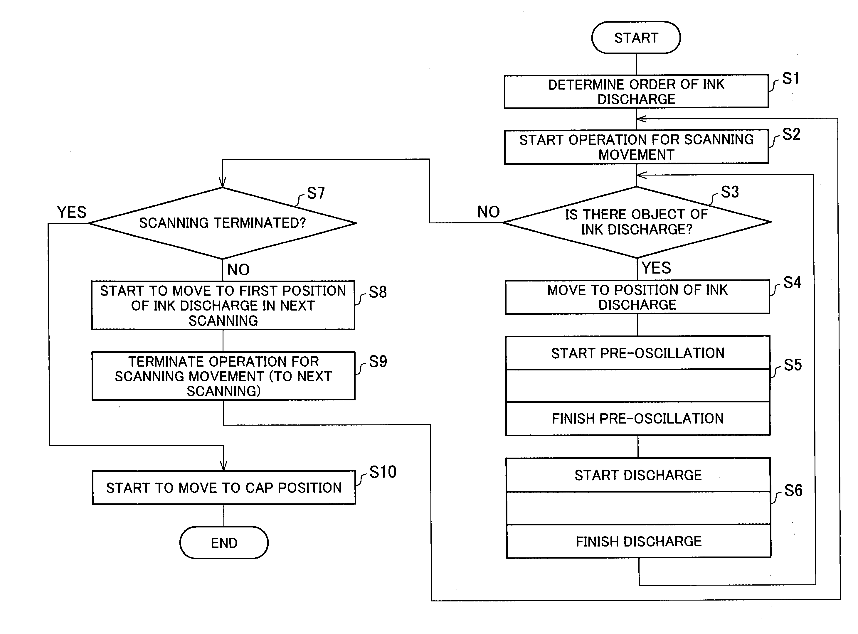
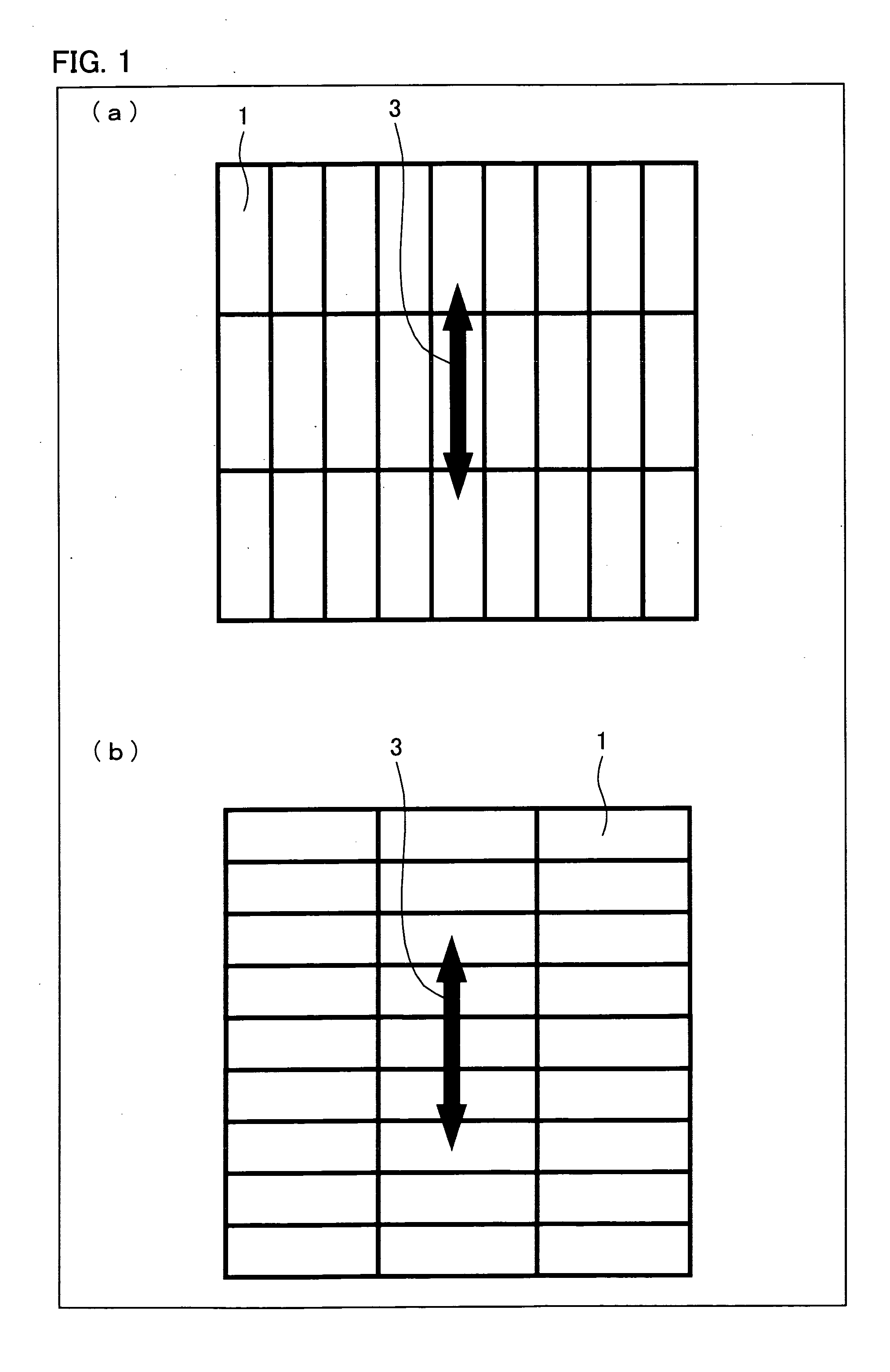
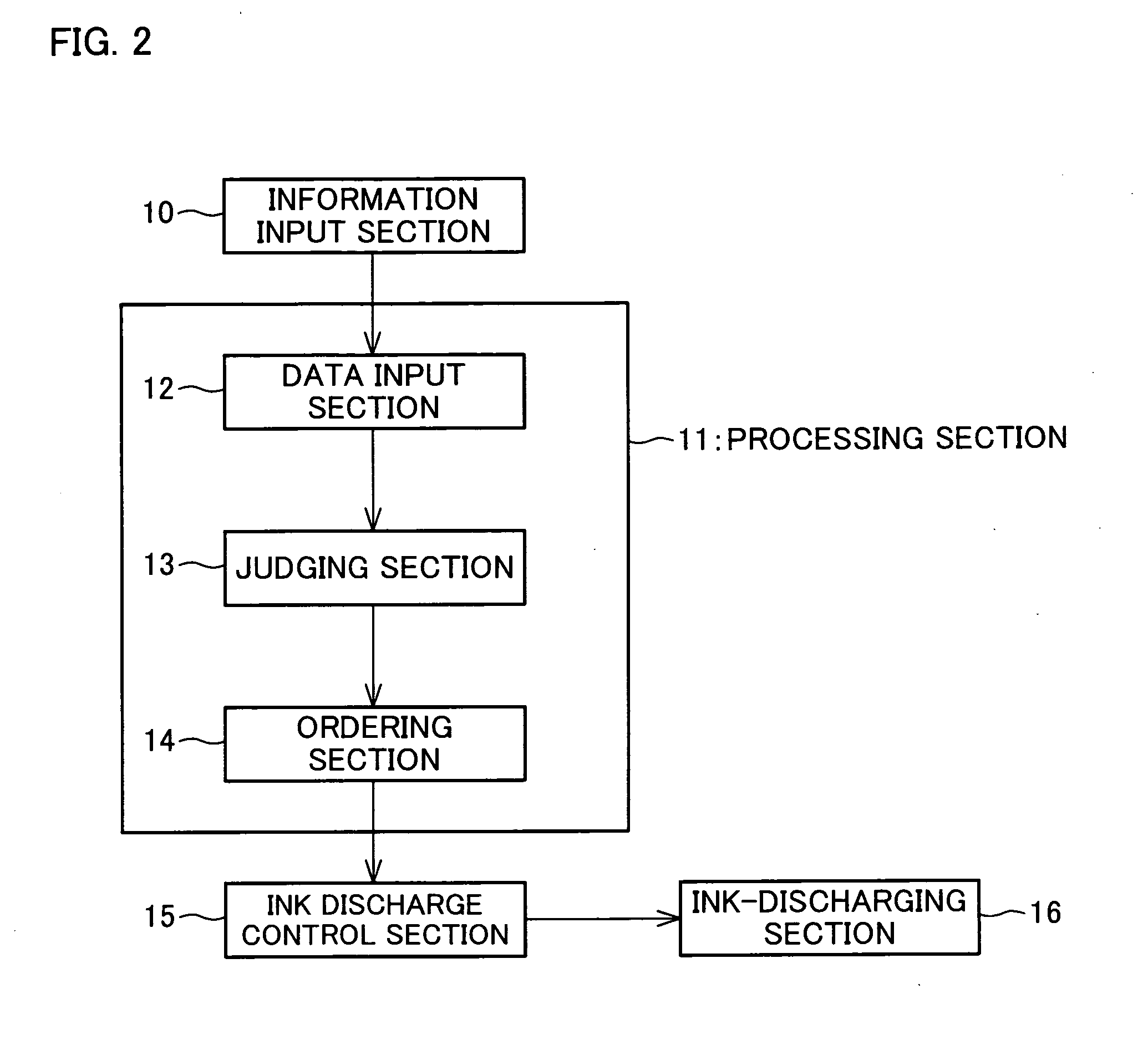
[0062]An ink-discharging apparatus according to the present invention is an ink-discharging apparatus including ink-discharging means. The ink-discharging means is a component, capable of moving relative to a medium along main scanning directions and sub-scanning directions so as to discharge ink at a group of targets of ink discharge scattered about on the medium, which moves at a constant velocity along the main scanning directions. The group of targets of ink discharge includes (i) a plurality of targets of first-direction discharge at which the ink-discharging means discharges ink by identical scanning in a first one of the main scanning directions and (ii) a plurality of targets of second-direction discharge at which the ink-discharging means discharges ink by identical scanning in a second one of the main scanning direction...


PUM


Abstract

A discharging head turns from a main scanning direction into the opposite main scanning direction in a short period of time in moving from one target of ink discharge to another. An ink-discharging apparatus of the present invention is arranged such that: ink-discharging means takes longer to move from one target of positive-direction discharge (2a) to another (2c) along main-scanning directions than along sub-scanning directions and takes longer to move from one of the targets of negative-direction discharge (2b) to another (2b) along the main-scanning directions than along the sub-scanning directions; the ink-discharging means takes longer to move from the last one of the targets of positive-direction discharge (2a) to the first one of the targets of negative-direction discharge along the sub-scanning directions than along the main scanning directions, the last target of positive-direction discharge being a target of positive-direction discharge that the ink-discharging means scans last among the targets of positive-direction discharge, the first target of negative-direction discharge being a target of negative-direction discharge that the ink-discharging means scans first among the targets of negative-direction discharge; and the ink-discharging means starts to move along the sub-scanning directions toward the first target of second-direction discharge in starting to move from the last target of positive-direction discharge to the first target of negative-direction discharge.

Description

TECHNICAL FIELD[0001]The present invention relates to ink-discharging apparatuses and, in particular, to an ink-discharging apparatus whose ink-discharging means turns from a main scanning direction into the opposite main scanning direction.BACKGROUND ART[0002]In recent years, techniques for discharging ink, which have been originally used for consumer printers, have been widely diverted to liquid-crystal CFs (color filters) panel production apparatuses and other production apparatuses, and as such, have diversified their uses.[0003]An example of the uses is an ink-jet patterning technique for forming a pattern on a substrate with use of a technique for discharging ink. The ink-jet patterning technique is a technique of printing a micropattern directly on a substrate by discharging minute amounts of liquid such as ink from an ink-discharging apparatus. The ink-jet patterning technique, which replaces a conventional photolithographic method for generating a pattern with use of a vacu...

Claims


Application Information

Patent Timeline
IPC IPC(8): B41J23/00
CPCB41J3/28B41J25/003B41J2202/09
Inventor YOSHIOKA, CHIYOSHITAMURA, TOSHIHIRO
Owner SHARP KK
Why Eureka
Try Eureka