Release mechanism for telescoping slide assembly

a technology of release mechanism and telescoping slide, which is applied in the field of slides, can solve the problems of complex structure, user may unintentionally press the outer end of the lever, and the design of the previous design suffers from several, and achieves the effect of simple and compact structur

Inactive Publication Date: 2002-07-02
KING SLIDE WORKS CO LTD
View PDF5 Cites 141 Cited by
  • Summary
  • Abstract
  • Description
  • Claims
  • Application Information

AI Technical Summary

Benefits of technology

It is another object of the present invention to provide a simple and compact release mechanism for telescoping slide assembly.

Problems solved by technology

However, the previous design suffered from several disadvantages.
For example, user may unintentionally press the outer end of lever to activate the unlocking of slide due to the open, manual pressing design.
Also, it is complex in structure.
Moreover, such previous design is too bulky to install in many current cabinets.

Method used


Image

  • Release mechanism for telescoping slide assembly
  • Release mechanism for telescoping slide assembly
  • Release mechanism for telescoping slide assembly

Examples


Embodiment Construction

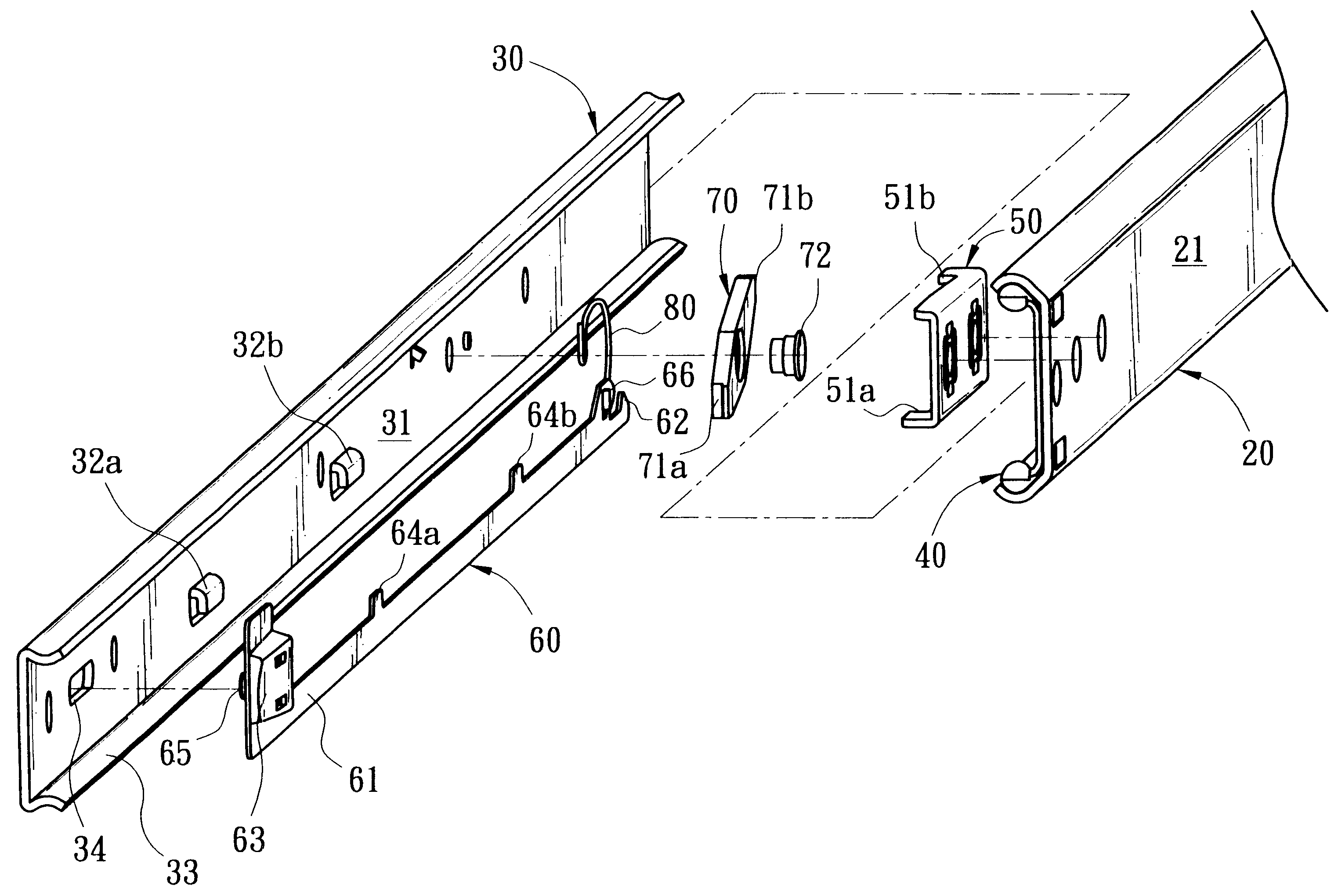
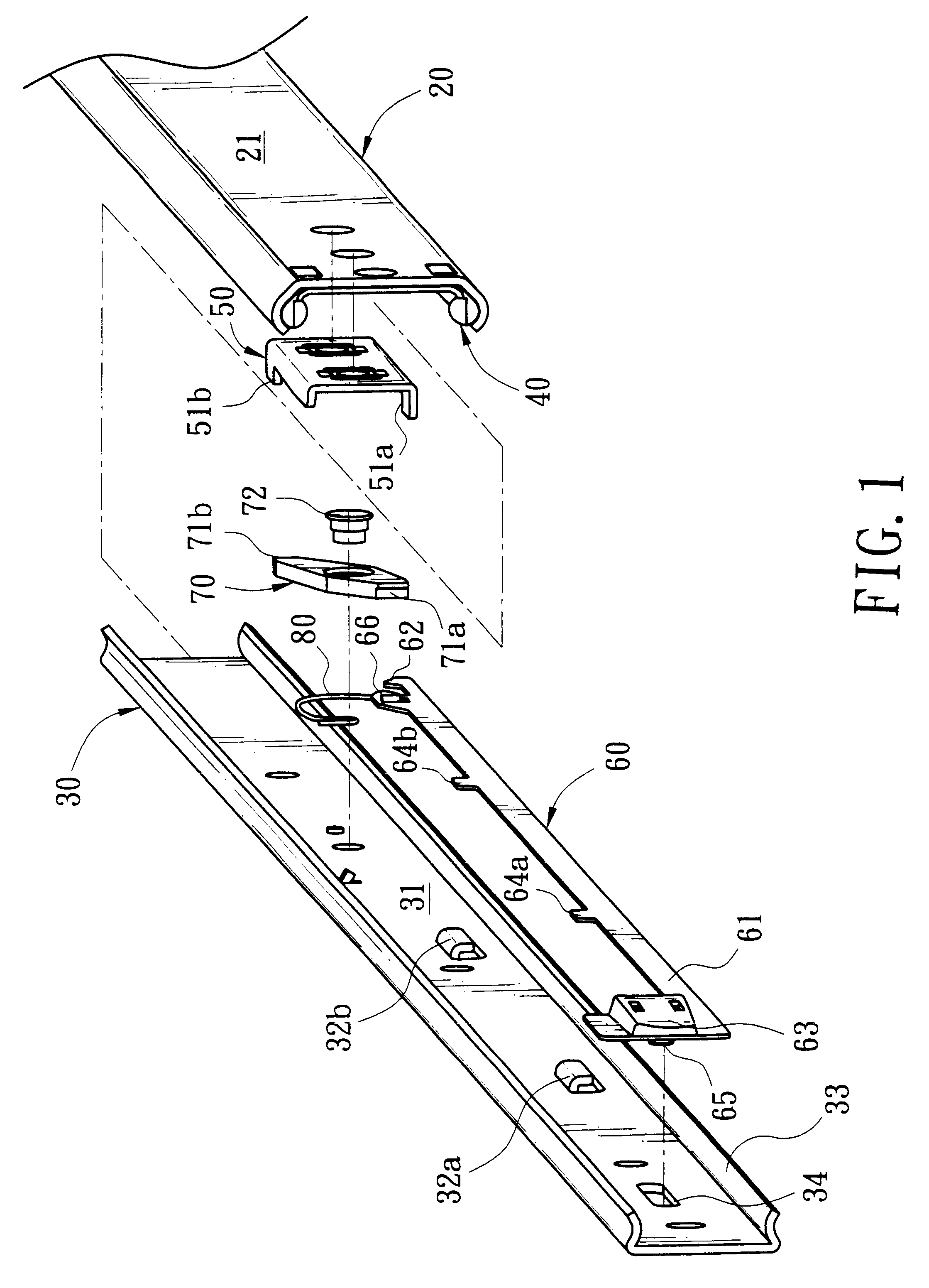
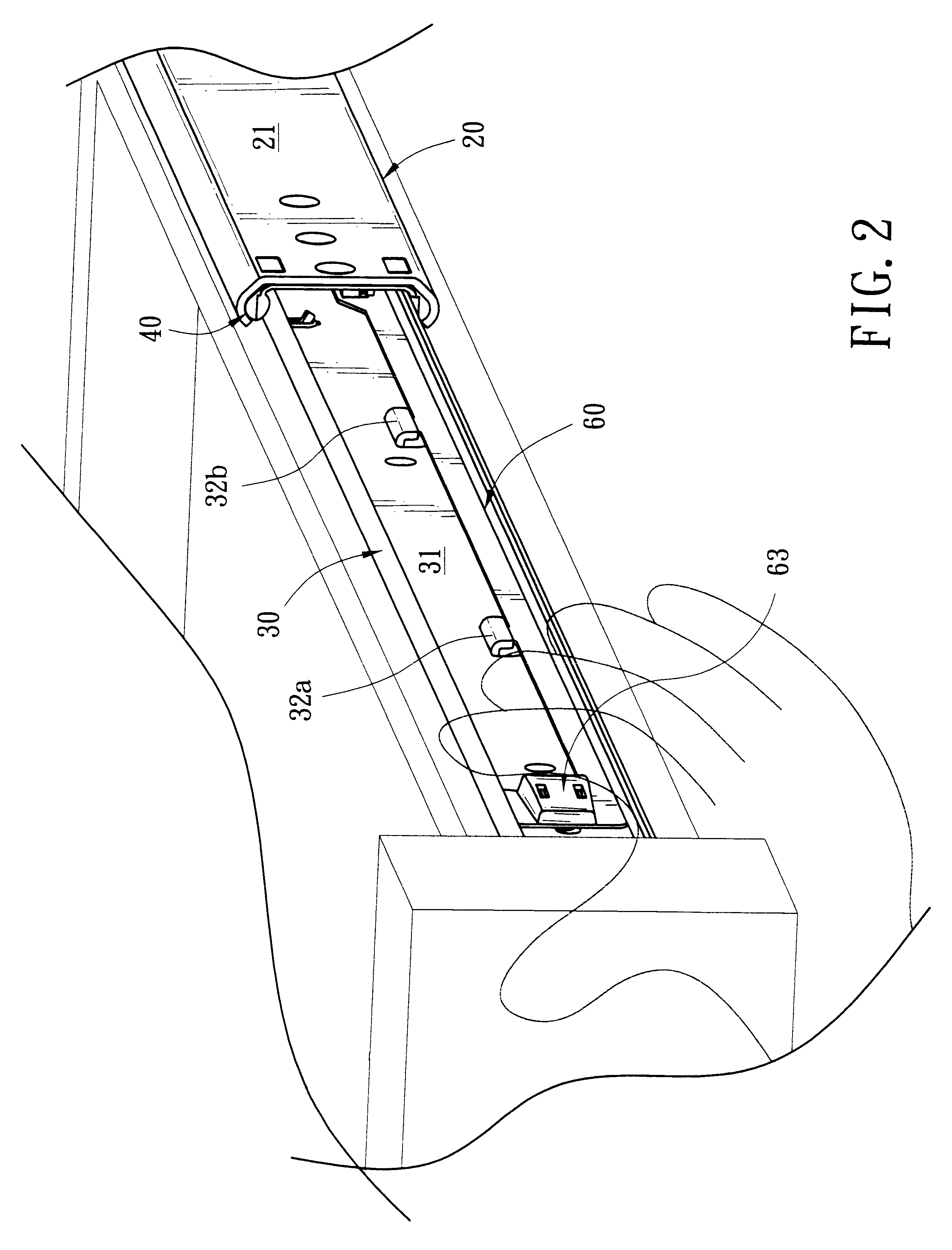
Referring to FIGS. 1 to 3, there is shown a telescoping slide assembly incorporating a release mechanism constructed in accordance with the invention. Slide comprises an outer member 20 and an inner member 30. This embodiment is implemented in a drawer and a cabinet combination wherein two pair of slides are employed to effectuate a relative sliding movement therebetween. Outer member 20 is affixed to the wall of cabinet. Inner member 30 is affixed to either side of drawer. Inner member 30 is slidably received in outer member 20. Typically, a ball bearing mechanism (e.g., ball bearings 40) is employed to interconnect inner and outer members 20 and 30. Hence, inner member 30 may coaxially move respect to outer member 20. When drawer is pulled out to its maximum extension, slide is also extended to a fully extended use position. Alternatively, user may retract the drawer into cabinet. Hence, the release mechanism of the invention may be activated so as to effect a locking of drawer wh...


PUM


Abstract

A release mechanism for telescoping slide including an outer member and an inner member is provided. The mechanism comprises an elongate connection member slidably mounted on the inner member. Operation performed on the access end of connection member at outer end of the slide may be transmitted to a pivot member near inner end of the slide. Thus pivot member may be selectively locked or unlocked for stopping or enabling the relative movement of the inner and the outer members. The push-pull style manipulation of the connection member is advantageous for having the open access end. Further, the structure is simplified for facilitating manufacture.

Description

BACKGROUND OF THE INVENTION1. Field of InventionThe present invention relates to the field of slides and more particularly to an improved release mechanism for telescoping slide assembly.2. Related ArtConventionally, a slide is widely employed to enable the relative movement of a drawer and a cabinet, a computer desk and a keyboard shelf, or the like. A conventional slide comprises an outer member and an inner member. For example in the drawer and cabinet configuration, outer member is fixedly attached to the wall of cabinet and inner member is fixedly attached to the side of drawer. Typically, a ball bearing mechanism is employed to interconnect above two members in a rolling relation. Hence, inner member may coaxially move respect to outer member. Thus drawer is permitted to remove to its maximum extension or retract into the cabinet. Conventionally, a stop mechanism such as latch is employed to lock the slide in a fully extended position when the slide reaches its maximum extensi...

Claims


Application Information

Patent Timeline
Patent Type & Authority Patents(United States)
IPC IPC(8): A47B88/04A47B88/16A47B88/14
CPCA47B88/14A47B88/16A47B88/487A47B88/57
Inventor LIANG, HSIU-CHIANGCHEN, KENG-CHINWANG, CHUN-CHIANG
Owner KING SLIDE WORKS CO LTD
Why Eureka
Try Eureka