Supercharge Your Innovation With Domain-Expert AI Agents!

Printing device

a printing device and printing plate technology, applied in printing, spacing mechanisms, printing mechanisms, etc., can solve the problems of loss of image quality, and shifts in the positions where the dots are formed

Inactive Publication Date: 2002-07-02
SEIKO EPSON CORP
View PDF10 Cites 18 Cited by
  • Summary
  • Abstract
  • Description
  • Claims
  • Application Information

AI Technical Summary

Problems solved by technology

In such cases, differences in the ink discharge properties of each nozzle can cause shifts in the positions where the dots are formed.
Feed errors during sub-scanning can also cause shifts in the positions where the dots are formed.
Such shifts can cause irregularities in density, referred to as banding, which can result in a loss of image quality.
In bi-directional printing, however, the positions where the dots are formed can sometimes shift in the primary scanning direction for various reasons, such as backlash in the mechanisms moving the head back and forth or errors in the head position detection.
However, this is only an extremely limited study, the object of which is merely a head with nozzles arranged at a pitch of 2 dots.
In such cases, there are no conventional examples studying whether pixels should be formed during forward or return travel to improve image quality.
Slight shifts in the dot forming positions are thus difficult to distinguish in the form of irregularities in density and the like, and have relatively little effect on image quality.
However, dots formed in different directions are adjacent to each other in the sub-scanning direction, and the direction in which they have been formed cannot be considered to be locally aligned.
The effect of such differences in surface area on image quality is relatively low, however, in the relatively high resolution printing executed by recent printing devices.
By contrast, as shown in FIG. 9, when shifts occur in several locations, the overall image quality becomes grainy, resulting in rougher printed images as a whole.
When shifts in the dot forming position occur while dots formed during forward travel and dots formed during return travel are present together in the raster lines, the dot density is quite easily discerned, tending to result in a loss of image quality.
When the resolution is changed, there may also be some changes in multi-tone ranges which are susceptible to readily discernible roughness.
When shifts occur in a large number of locations, the image as a whole will appear grainy, resulting in rougher images overall.

Method used


Image

  • Printing device
  • Printing device
  • Printing device

Examples


example 2

(3) Example 2

A second example of a printing device is described below. The hardware structure of the printing device in Example 2 is the same as that in Example 1. The flow chart of the dot forming routine is also the same as that in Example 1. The control parameter table and its separate uses in Example 2 are different from those in Example 1.

FIG. 11 illustrates an example of the control parameter table for Example 2. Here, only the sub-scan feed for natural image printing mode is shown. The feed corresponds to a case of 96 nozzles at a pitch of 4 dots. As shown in the figure, sub-scanning in Example 2 is performed at different feeds according to the resolution during printing.

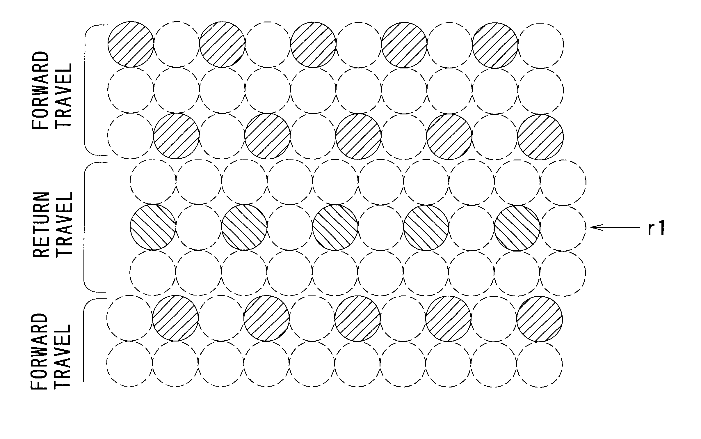
Auxiliary scanning is performed at a constant feed of 47-dot segments when the printing mode has a low resolution, that is, a resolution of 360 DPI (dots per inch) in the primary scanning direction and a resolution of 720 DPI in the sub-scanning direction. FIG. 12 illustrates the appearance of the dots formed...


PUM


Abstract

The invention comprises a printing device wherein a head comprising a plurality of nozzles at a predetermined pitch is used for repeated primary scanning and sub-scanning to print images. The primary and sub-scanning are carried out in such a way as to comply with the following conditions. In the case of printing at a high resolution, dots are first formed during bi-directional operation of the primary scan. Second, the direction in which the dots are formed is aligned for each raster line. Third, a plurality of raster lines formed during operation in the same direction are adjacent to each other. Dots are formed under such conditions to allow the direction in which the dots are formed to be locally aligned. That is, locations with easily discernible shifts in the dots formed during forward travel and the dots formed during return travel can be reduced, allowing the grainy look of images to be improved.

Description

1. Field of the InventionThe present invention relates to a printing device and method for forming dots during the movement of a head as it travels back and forth to print multi-colored multi-tone images on a printing medium, and to a recording medium on which is recorded a program for such printing.2. Description of the Related ArtVarious printers have been used in the past as computer or digital camera output devices. Such printers include ink jet printers that jet ink to form dots and print multi-colored multi-tone images. In ink jet printers, dots are formed for each pixel by repeated primary scanning, in which the head travels back and forth, and sub-scanning, in which the printing paper is conveyed. Dots are formed by ink of predetermined colors, and multiple colors are brought out by the overlapping of these inks. The tones of images are brought out by the dot recording density.Ink jet printers commonly make use of multinozzles comprising a plurality of nozzles arranged at a ...

Claims


Application Information

Patent Timeline
Patent Type & Authority Patents(United States)
IPC IPC(8): B41J19/14B41J11/42B41J19/00B41J2/21B41J2/01B41J2/51B41J2/525
CPCB41J2/2132B41J11/42B41J19/142B41J19/145
Inventor TAYUKI, KAZUSHIGEFUJIMORI, YUKIMITSUOTSUKI, KOICHI
Owner SEIKO EPSON CORP
Features
  • R&D
  • Intellectual Property
  • Life Sciences
  • Materials
  • Tech Scout
  • Unparalleled Data Quality
  • Higher Quality Content
  • 60% Fewer Hallucinations
Learn More