Self drilling swivel toggle anchor

a toggle anchor and self-drilling technology, applied in the field of toggle anchors, can solve the problems of not being able to self-drill the device, nail or screw cannot hold fast in plaster, thin plywood, metal siding,

Inactive Publication Date: 2002-08-20
BLACK & DECKER INC
View PDF18 Cites 76 Cited by
  • Summary
  • Abstract
  • Description
  • Claims
  • Application Information

AI Technical Summary

Benefits of technology

Another object of the present invention is to provide a toggle design that significantly reduces the endwise profile so that a smaller hole can be drilled relative to the diameter of the anchor member. Still another object of the invention is to reduce the number of mechanical parts needed to fabricate a toggle anchor. Again, an object of this invention is to provide such a toggle anchor made essentially or entirely of plastic.
The toggle member is releasably lockable in the first position to the anchor member to provide even distribution of a torque applied to the anchor member along the length of the device. The locking portion of the anchor member features a rim recessed from the distal end of the anchor member and support projections extending from the distal end of the anchor member. The rim and the support projections define and border a locking groove which receives and locks the toggle member in the first position. The toggle member is provided with a fitting portion that is adapted to frictionally engage the locking groove and secure the toggle member in linear engagement with the anchor member. The toggle member is also provided with tracks that receive ribs located on the inner surface of central portions of the anchor member and protrude into the channel. As torque is applied to the head portion of the anchor member, via a screwdriver, the torque is evenly distributed to the working end of the device, i.e., the self drilling end which is provided with a plurality of drilling blades or any conventional device for efficient drilling. In essence, a combination of the interaction of the upper and lower pairs of shoulders supporting and containing the body, the locking portion of the anchor member and the fitting portion of the toggle member, and the ribs of the anchor member and the tracks of the toggle member ensures that the torque is distributed evenly throughout the toggle anchor while drilling through a sheet rock wall having a hollow chamber.

Problems solved by technology

Securing hardware to walls that have hollow spaces presents a particularly difficult problem to solve.
Typically, a nail or screw will not hold fast in plaster, gypsum, thin plywood, metal siding or other such materials that are not backed up by a solid reinforcing member such as a stud, joist, or the like.
However, the device is not self drilling and a hole must first be drilled before the toggle anchor is placed in the wall.
This can create undesirable shear forces between contact points of the anchor member and the toggle member which can cause the toggle anchor to burrow offline from the intended target area, misalign the seating of the toggle anchor, and possibly separate the toggle member from the anchor member.

Method used


Image

  • Self drilling swivel toggle anchor
  • Self drilling swivel toggle anchor
  • Self drilling swivel toggle anchor

Examples


Embodiment Construction

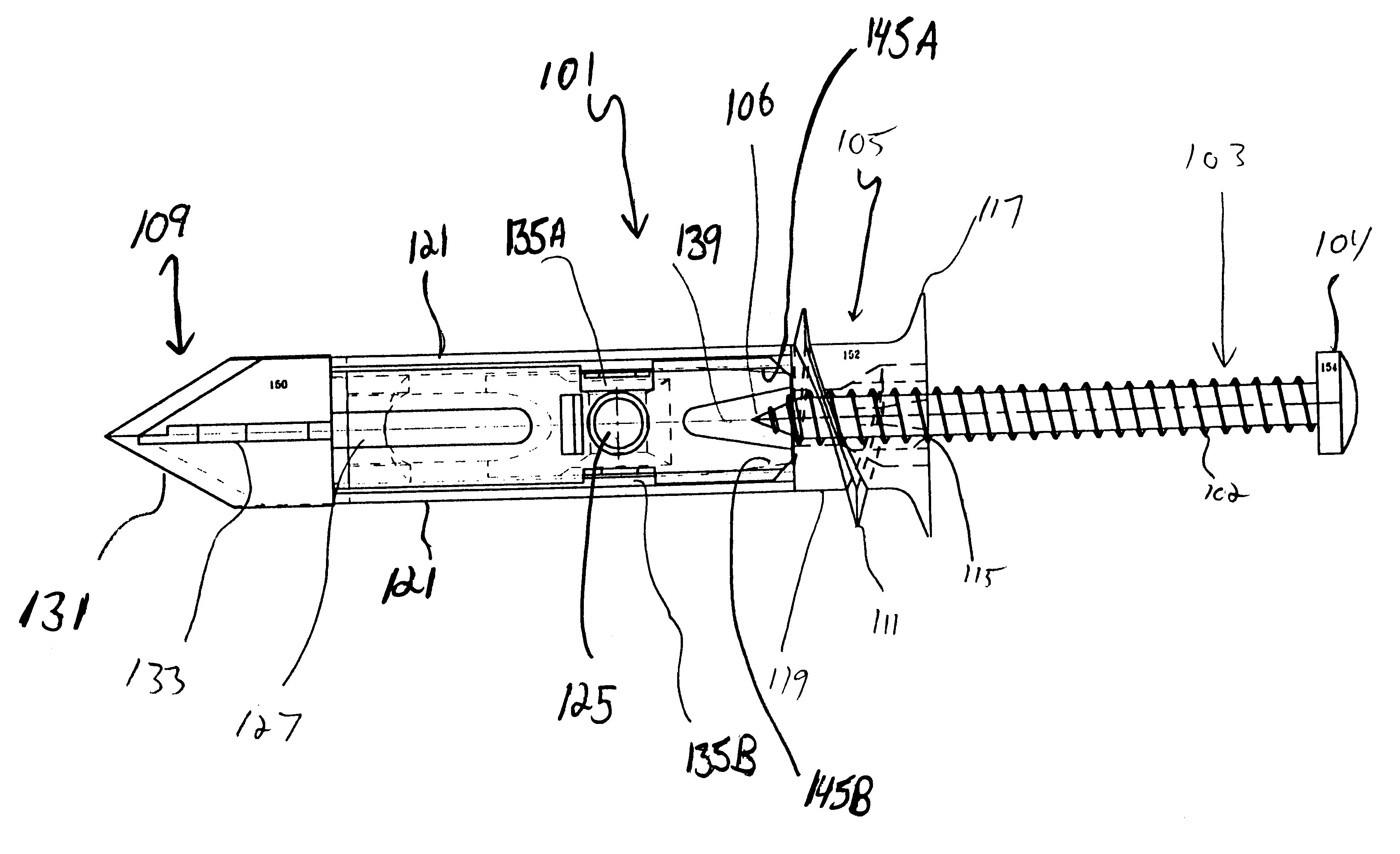
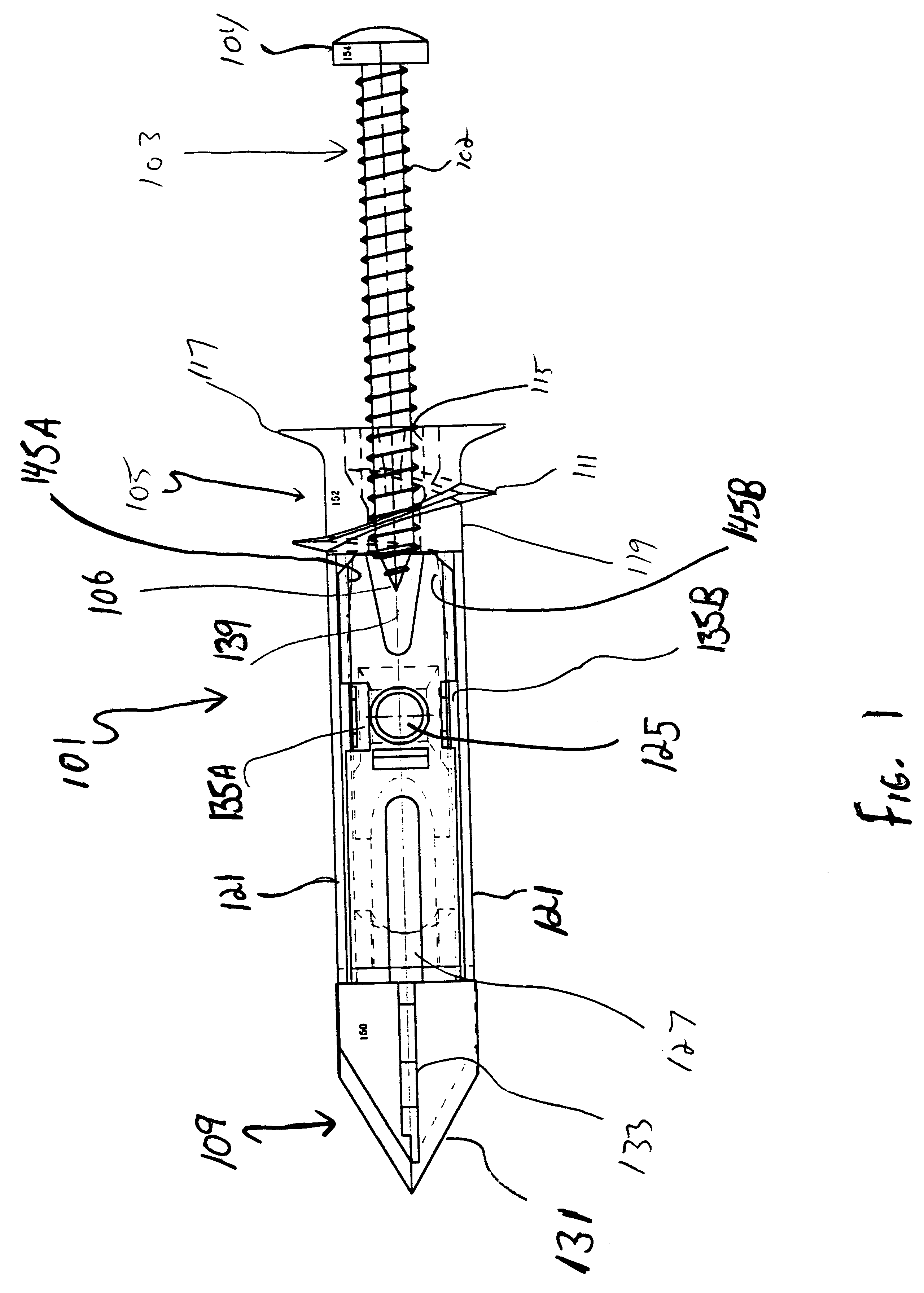
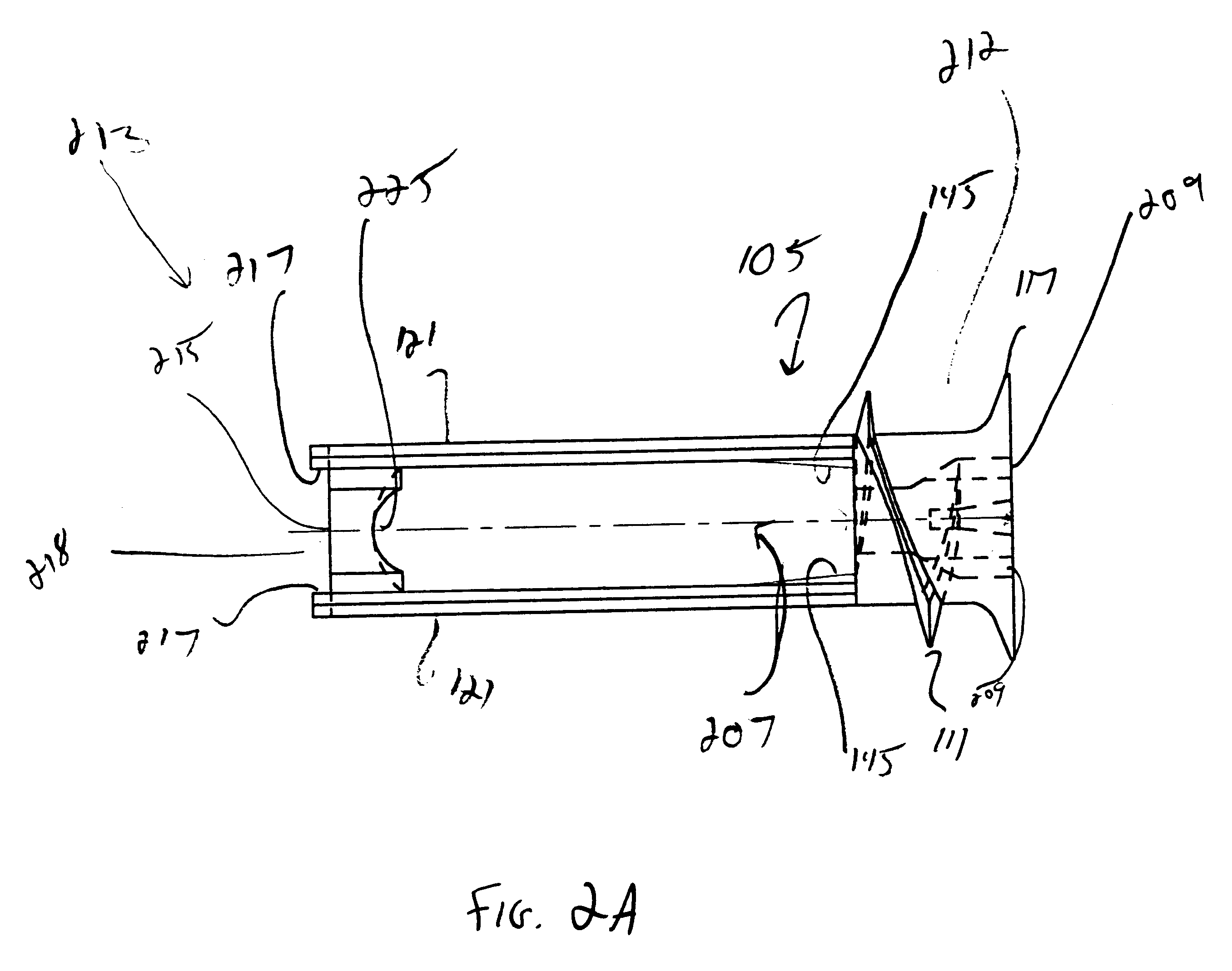
Referring initially to FIGS. 1, 2A, 2B, and 2C, there is shown a toggle anchor generally at 101 having an anchor member 105 and a self drilling toggle member 109. Anchor member 105 includes head portion 212 at a proximal end and at a distal end a locking portion 213.

Head portion 212 is cylindrycal and comprises external threads 111 and a counter sunk support lip 117. Support lip 117 may be the shape of any conventional driving head or recess, e.g. hex, flat head, phillips, driver, etc. Bore 205 extends through head portion 212 along the longitudinal axis thereof and is adapted to receive a self tapping threaded screw or bolt 103.

As shown in FIG. 1, screw 103 is partially transposed into bore 205. Walls 115 of bore 205 are engaged by threads 102 of screw 103. Diametrically opposed slots 209 are counter sunk in walls 115 surrounding bore 205. Slots 209 are adapted to receive the working end of a driver, as such as flat head screwdriver (not shown). It is understood that any convention...


PUM


Abstract

A self drilling toggle anchor including an anchor member having a head portion at a proximal end, a locking portion at a distal end and a central portion for securely anchoring hardware to a wall, where the central portion defines and borders a channel between the head portion and locking portion. The toggle anchor also includes a drilling member positioned at a distal end of the toggle anchor for drilling through the wall and a toggle member. The toggle member includes a body disposed within the channel of the anchor member, a fitting portion disposed between the body and the drilling member, and upper and lower pairs of shoulders supporting the body within the channel. The body is slidably mounted to the anchor member within the channel and the fitting portion is adapted to releasably engage the locking portion allowing the toggle member to be movable from a releasably locked and fixed first position parallel with a longitudinal axis of the channel to a second position orthogonal to the channel.

Description

BACKGROUND THE INVENTIONThe present invention generally relates to toggle anchors for securing hardware to walls, and specifically to toggle anchors that have threaded anchor members and a lockable self drilling swivel toggle member.Securing hardware to walls that have hollow spaces presents a particularly difficult problem to solve. Typically, a nail or screw will not hold fast in plaster, gypsum, thin plywood, metal siding or other such materials that are not backed up by a solid reinforcing member such as a stud, joist, or the like. The traditional prior art approach to this problem has resulted in the well-known toggle anchor or toggle bolt. The standard toggle anchor typically consists of numerous parts including a body portion having a retainer bar pivotally attached to its inner end, usually articulated and pivotable about a hinge, and kept in an open axial position by a spring bias. In addition, a nut and bolt combination is provided as a central axis about which the hinged ...

Claims


Application Information

Patent Timeline
Patent Type & Authority Patents(United States)
IPC IPC(8): F16B13/08F16B13/00F16B13/04
CPCF16B13/002F16B13/0808
Inventor GAUDRON, PAUL
Owner BLACK & DECKER INC
Why Eureka
Try Eureka