
Retroreflective article

a retroreflective and article technology, applied in the direction of roads, instruments, traffic signals, etc., can solve the problems of light refracting ability, much reduced retroreflective performance, and reduced retroreflective brightness

Inactive Publication Date: 2002-09-17
3M INNOVATIVE PROPERTIES CO
View PDF48 Cites 48 Cited by
  • Summary
  • Abstract
  • Description
  • Claims
  • Application Information

AI Technical Summary

Benefits of technology

Another advantage of the present invention is that the retroreflective article is visible from any direction, as the reflectivity is high regardless of the direction of approach of the viewer to the article. This omni-directional feature makes the invention particularly well suited for horizontal applications, such as intersection markings, where vehicles may approach from a number of angles.

Problems solved by technology

During rainy periods, the microspheres become wetted with water which reduces their light refracting ability resulting in much reduced retroreflective performance.
At distances greater than this, retroreflective brightness declines due in part to the relatively larger entrance angles of the incident light and in part to inherently limited retroreflective brightness.
In addition to generally low retroreflectivity at high incidence angles, flat pavement markings are particularly difficult to see under rainy conditions for the reasons discussed above.
However, snow removal is frequently a problem on roads bearing raised pavement markers, as the snowplows have a tendency to catch on the raised protrusions and dislodge the markers from the road surface.
Also, raised pavement markers mounted as spot delineators provide relatively poor daytime road delineation and thus commonly need to be augmented with continuous painted or tape line markings.

Method used


Image

  • Retroreflective article
  • Retroreflective article

Examples


examples

The invention will be further explained by the following illustrative examples that are intended to be non-limiting.

Retroreflectivity Measurements Under Dry and Dynamic Wet Conditions

Dry and wet coefficients of Retroreflected Luminance (R.sub.L) were measured for Examples 1-9 and Comparative Example A in accordance with ASTM E809 entitled Standard Practice for measuring Photometric Characteristics of Retroreflectors and ASTM D 4061-94 entitled Test Method for Retroreflectance of Horizontal Coatings.

In each case, the reflective articles to be evaluated were applied to flat aluminum panels and placed on a horizontal surface, to simulate a pavement marking applied to a road surface. R.sub.L was measured under dry and wet conditions at a simulated viewing distance of 30 meters. A Gamma Scientific Photometer Model 2009 (formerly Gamma Scientific now Advanced Retro Technology, Inc. Spring Valley, Calif.) with a Gamma Scientific Model RS-50 lamp was used to make the measurements. The obser...

examples 1-9

were prepared sprinkling various amounts of retroreflective elements to the bonding composition. Once the retroreflective elements were applied to the bonding composition, each sample was cured and dried in an oven at a temperature of about 260.degree. F. (127.degree. C.) for about 20 minutes.

TABLE 2 illustrates the amount of retroreflective element used in the various samples, along with the approximately surface area coverage of those elements. Skid resistance values, as measured by ASTM E303, are also reported. It should be noted that Comparative Example A represented the retroreflective sheeting with no retroreflective elements on the top surface of it, and corresponds to Sample 7 of TABLE 1.

Preferably, a minimum value of about 45 BPN to about 55 BPN is suitable for pavement marking applications. The data above illustrates an increase in BPN as the percent surface area of the article covered by the retroreflective elements is increased until an optimum is reached. A maximum valu...


PUM

PropertyMeasurementUnit
coefficient of retroreflective luminanceaaaaaaaaaa
diameteraaaaaaaaaa
refractive indexaaaaaaaaaa

Abstract

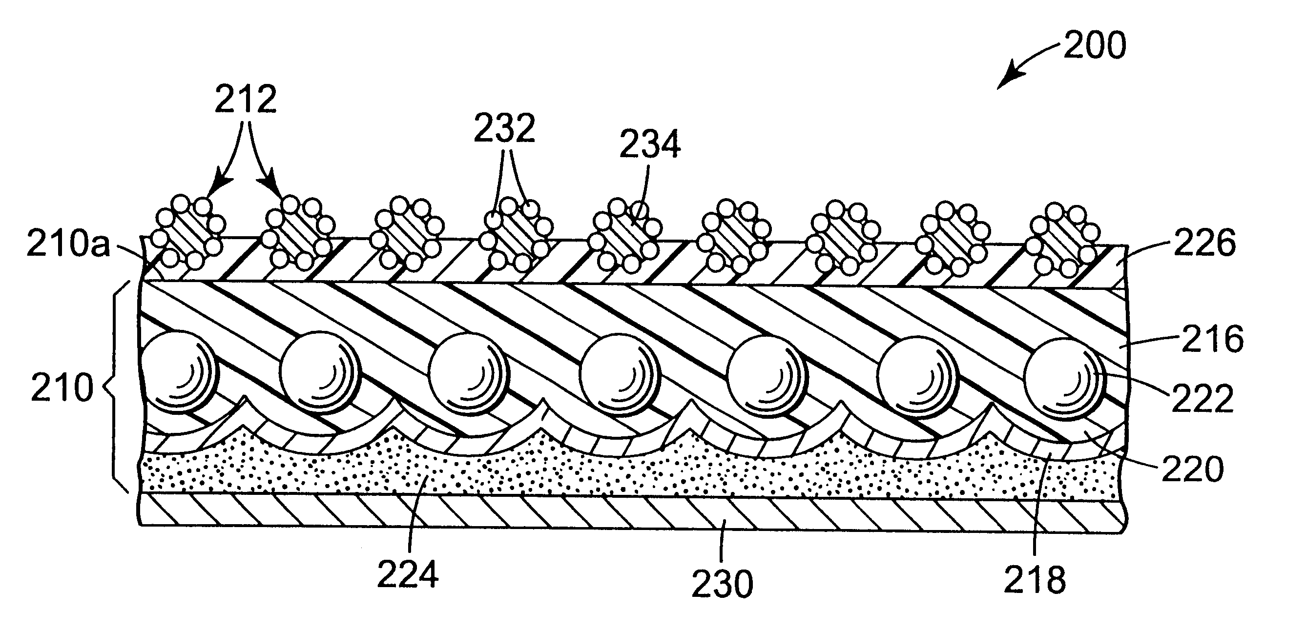
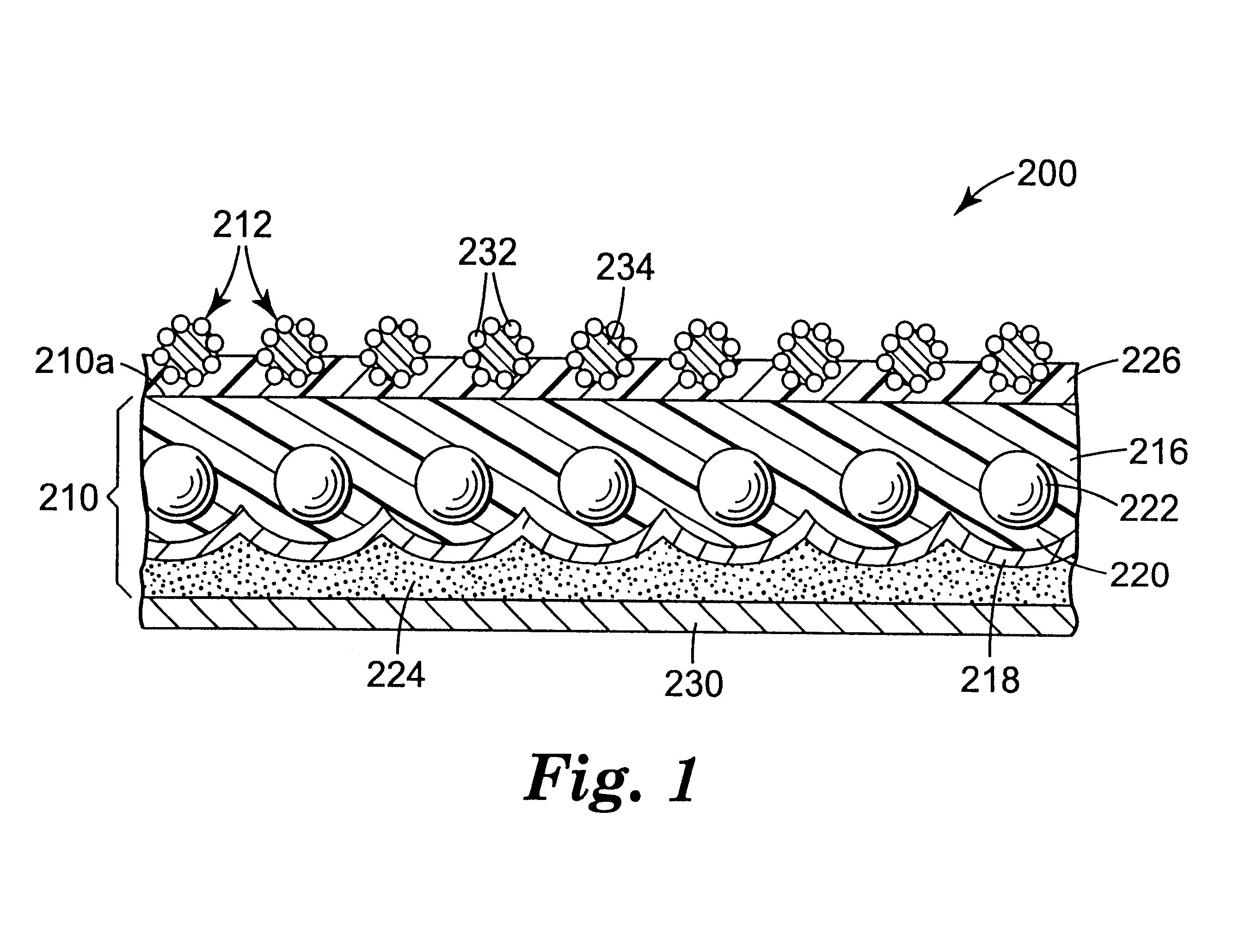
A retroreflective article that exhibits suitable retroreflective luminance under dry and dynamic wet conditions. The article includes an enclosed-lens retroreflective sheeting that, under dry conditions, exhibits a coefficient of retroreflective luminance of about 40 (millicandela / m2) / lux as measured by ASTM D 4061-94 and, under dynamic wet conditions the sheeting increases in coefficient of retroreflective luminance. The article further includes a plurality of retroreflective elements partially embedded in a light transmissible bonding layer on the front, reflective surface of the retroreflective sheeting.

Description

The present invention relates to retroreflective articles that exhibit good retroreflective brightness under wet and dry conditions and good retroreflective brightness at high entrance angles.Pavement markings, such as those on the centerline and edgeline of a roadway, are important in order to provide visual guidance for motor vehicle drivers. Pavement marking materials are used as traffic control markings for a variety of uses, such as short distance lane striping, stop bars, and pedestrian pavement markings at intersections and long line lane markings, etc. on roadways. A common form of pavement marking material is adhesive-backed tape that is applied to the roadway surface in desired location and length; the top surface of the tape having selected color and typically retroreflective characteristics.Currently, many flat pavement markings typically rely on an exposed-lens optical system comprising transparent microspheres partially embedded in a binder layer containing reflective ...

Claims


Application Information

Patent Timeline
Patent Type & Authority Patents(United States)
IPC IPC(8): E01F9/011E01F9/03E01F9/04E01F9/015G02B5/128G02B5/12E01F9/619E01F9/08E01F9/669
CPCE01F9/015E01F9/042E01F9/044G02B5/128E01F9/03Y10T428/24355Y10T428/24372Y10T428/24479Y10T428/28Y10T428/24562Y10T428/24529Y10T428/24537Y10T428/252Y10T428/24521Y10T428/24421E01F9/619E01F9/669E01F9/512E01F9/524
Inventor HAUNSCHILD, DALE H.ETHEN, JOHN L.ZENDER, MARK D.HAENGGI, ROBERT A.STUMP, LARRY K.
Owner 3M INNOVATIVE PROPERTIES CO
Learn More