
Nerve proximity and status detection system and method

a technology of proximity and status detection and nerves, applied in the field of nerve proximity and status detection methods and systems, can solve the problems of limiting the ability of users to detect the response, and difficult to adapt to the competing tasks of users

Inactive Publication Date: 2002-10-15
NUVASIVE
View PDF67 Cites 592 Cited by
  • Summary
  • Abstract
  • Description
  • Claims
  • Application Information

AI Technical Summary

Problems solved by technology

This may be difficult depending on the competing tasks of the user.
In addition, when general anesthesia is used during a procedure, muscular response may be suppressed, limiting the ability of a user to detect the response.

Method used


Image

  • Nerve proximity and status detection system and method
  • Nerve proximity and status detection system and method
  • Nerve proximity and status detection system and method

Examples


Embodiment Construction

Throughout this description, the preferred embodiment and examples shown should be considered as exemplars, rather than as limitations on the present invention.

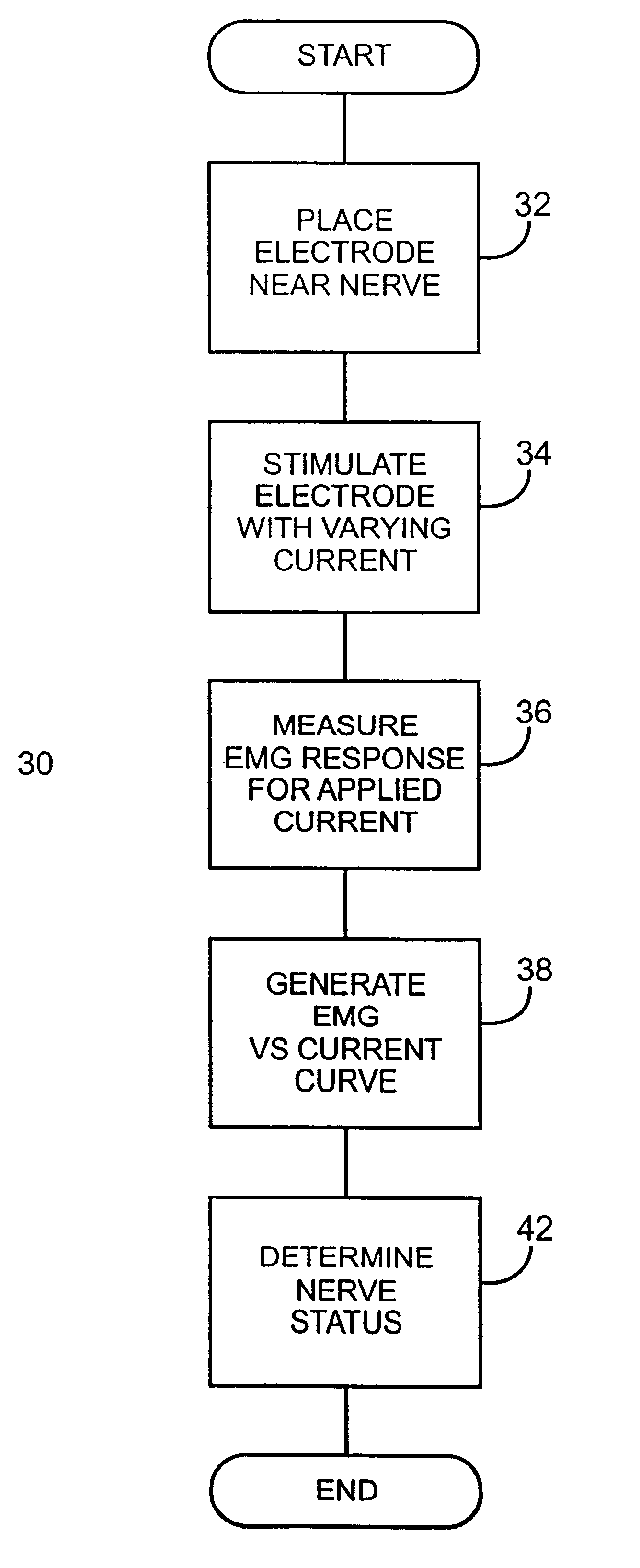
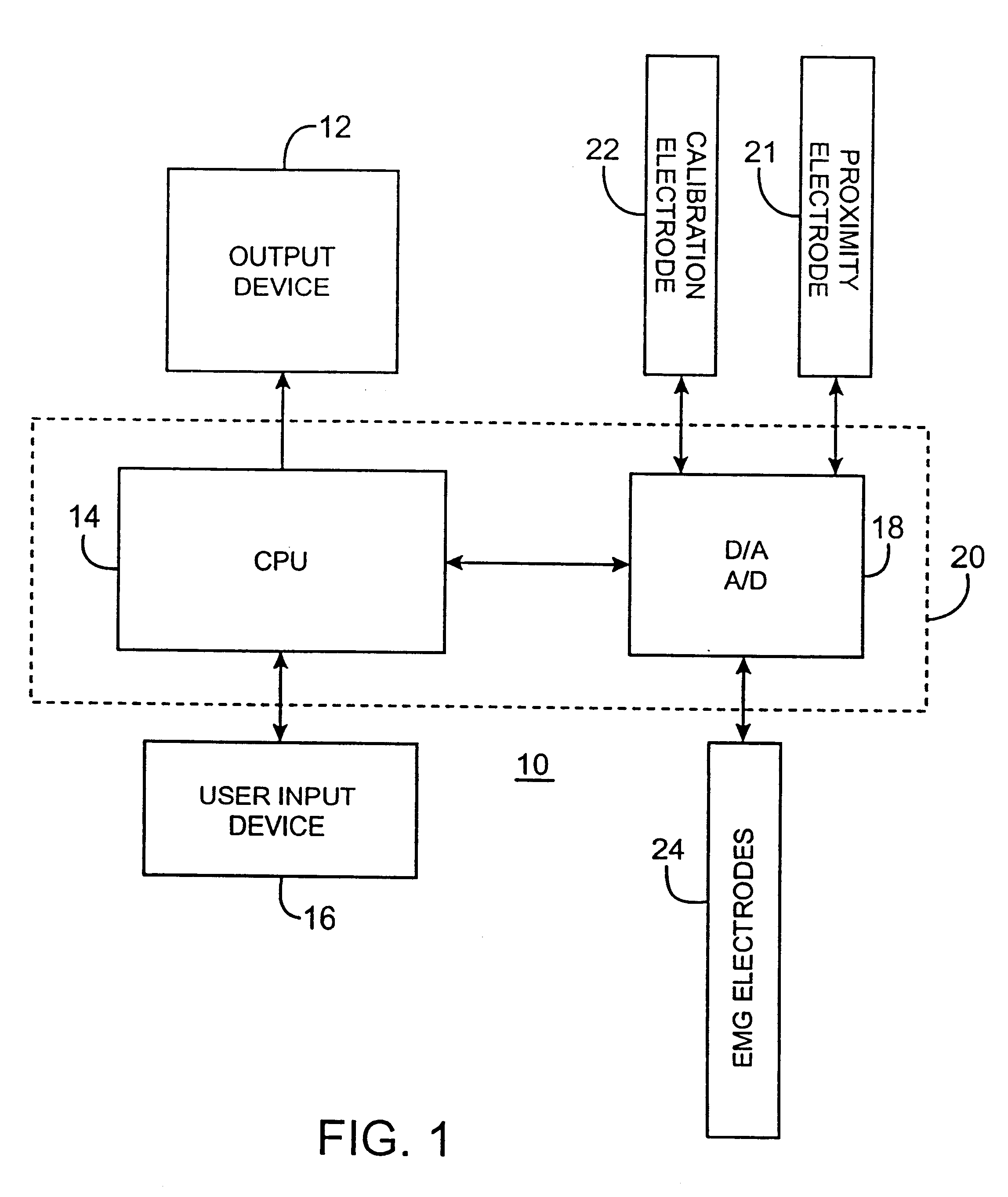
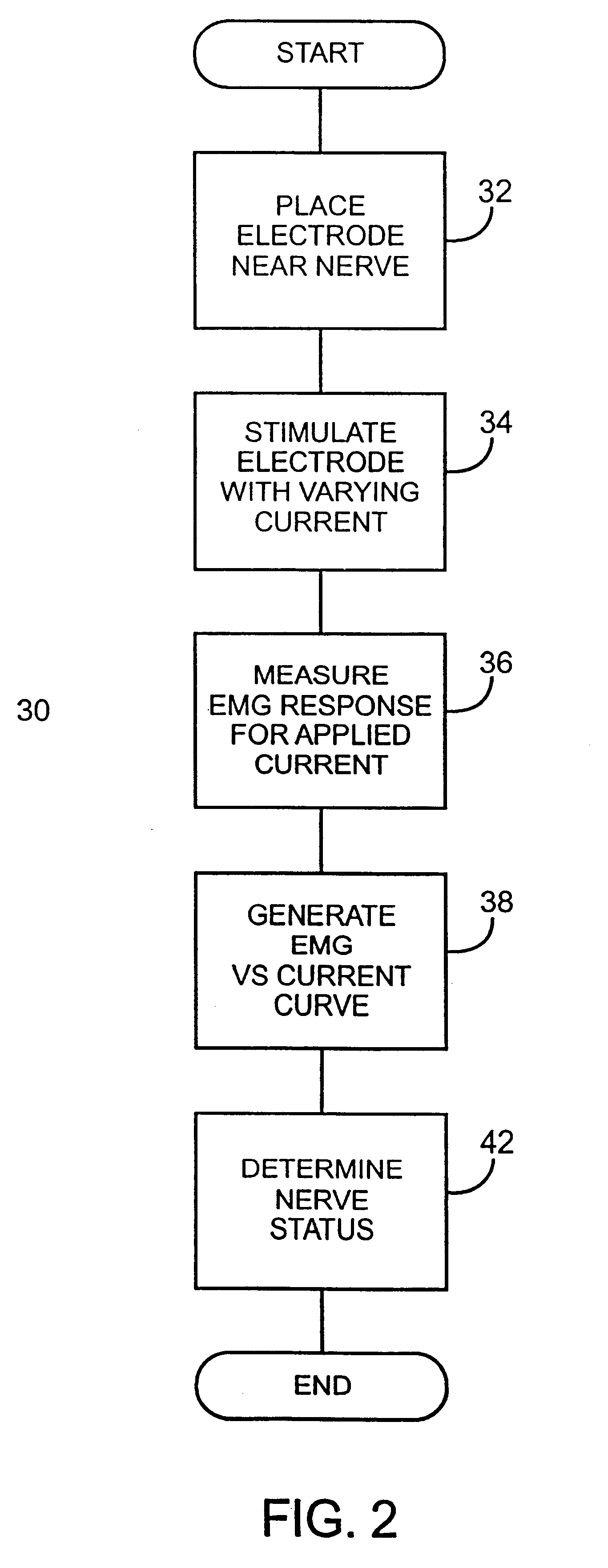
FIG. 1 is a diagram of a nerve status and proximity system 10 in accordance with the present invention. The system 10 includes an output device 12, a user input device 16, a processor 20, a proximity electrode 21, a calibration electrode 22, and an electromyogram (EMG) electrode 24. The processor 20 includes a central processing unit ("CPU") 14 and a Digital to Analog converter ("D / A") and Analog to Digital Converter ("A / D") 18. The CPU 14 may be any microprocessor having sufficient processing power to control the operation of the D / A & A / D 18, and output device 12. The D / A & A / D 18 is any such device having a sufficient operating cycle to generate signals as described herein and a sufficient sampling rate. The calibration electrode 22 is an electrode suitable for placement near a nerve of a patient to be monitored. The EMG e...


PUM


Abstract

A method and system for detecting proximity of a nerve to a proximity electrode and status of nerve. The method of detecting the proximity of the nerve to the proximity electrode applies a first electrical signal with multiple current levels to a calibration electrode. The method applies a second electrical signal with multiple current levels to the proximity electrode. Based on the response of the nerve to the first and second electrical signals, the method determines the proximity of the proximity electrode to the nerve. The method determines the status of the nerve by applying the first electrical signal with multiple signal levels to the calibration electrode.

Description

1. Field of the InventionThis invention relates to nerve monitoring systems and to nerve muscle monitoring systems, and more particularly to nerve proximity and status detection methods and systems.2. Description of Related ArtSystems and methods exist for monitoring a nerve. One such system determines when a needle is approaching a nerve. The system applies a current to the needle to evoke a muscular response. The muscular response is visually monitored, (typically as a shake or "twitch"). When such a muscular response is observed by the user, the needle is considered to be near the nerve coupled to the responsive muscle. These systems require the user to observe the muscular response (to determine that the needle has approached the nerve). This may be difficult depending on the competing tasks of the user. In addition, when general anesthesia is used during a procedure, muscular response may be suppressed, limiting the ability of a user to detect the response.Accordingly, a need e...

Claims


Application Information

Patent Timeline
Patent Type & Authority Patents(United States)
IPC IPC(8): A61B5/0488A61B5/04A61B5/0492A61B5/296A61B17/00A61B19/00
CPCA61B5/04001A61B5/0488A61B5/4893A61B5/0492A61B2017/00039A61N1/08A61B5/24A61B5/296A61B5/389A61B5/395
Inventor KAULA, NORBERT F.BLEWETT, JEFFREY J.MARINO, JAMES F.
Owner NUVASIVE
Learn More