Display apparatus

a technology of display apparatus and display screen, which is applied in the field of display screen, can solve the problems of image data not being written in sufficient quantity, image quality degradation of displayed image,

Inactive Publication Date: 2002-10-29
VIDEOCON GLOBAL
View PDF13 Cites 127 Cited by
  • Summary
  • Abstract
  • Description
  • Claims
  • Application Information

AI Technical Summary

Problems solved by technology

A problem in this scheme is that when the displayed image is changed for each frame period to display the motion picture, the displayed image of the one frame period remains in the human eyes as an afterimage and this afterimage overlaps with the display image of the next frame period, so that the image quality of the displayed image is degraded. FIG. 2 shows a timing diagram of a prior scheme for solving the problem of the afterimage caused in the scheme shown in the FIG. 1.
Although this scheme solves the problem of the afterimage, this scheme causes a new problem that the width of the g

Method used


Image

  • Display apparatus
  • Display apparatus
  • Display apparatus

Examples


first embodiment

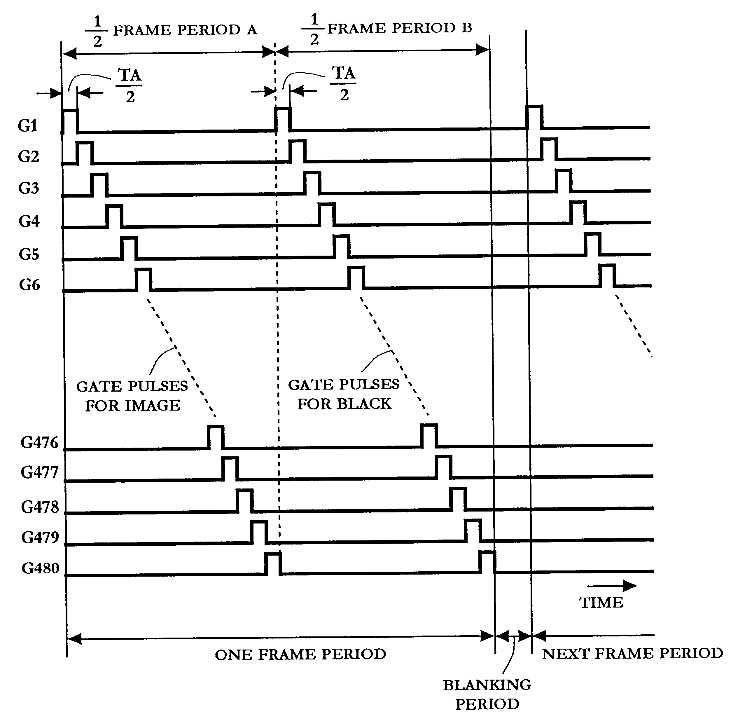
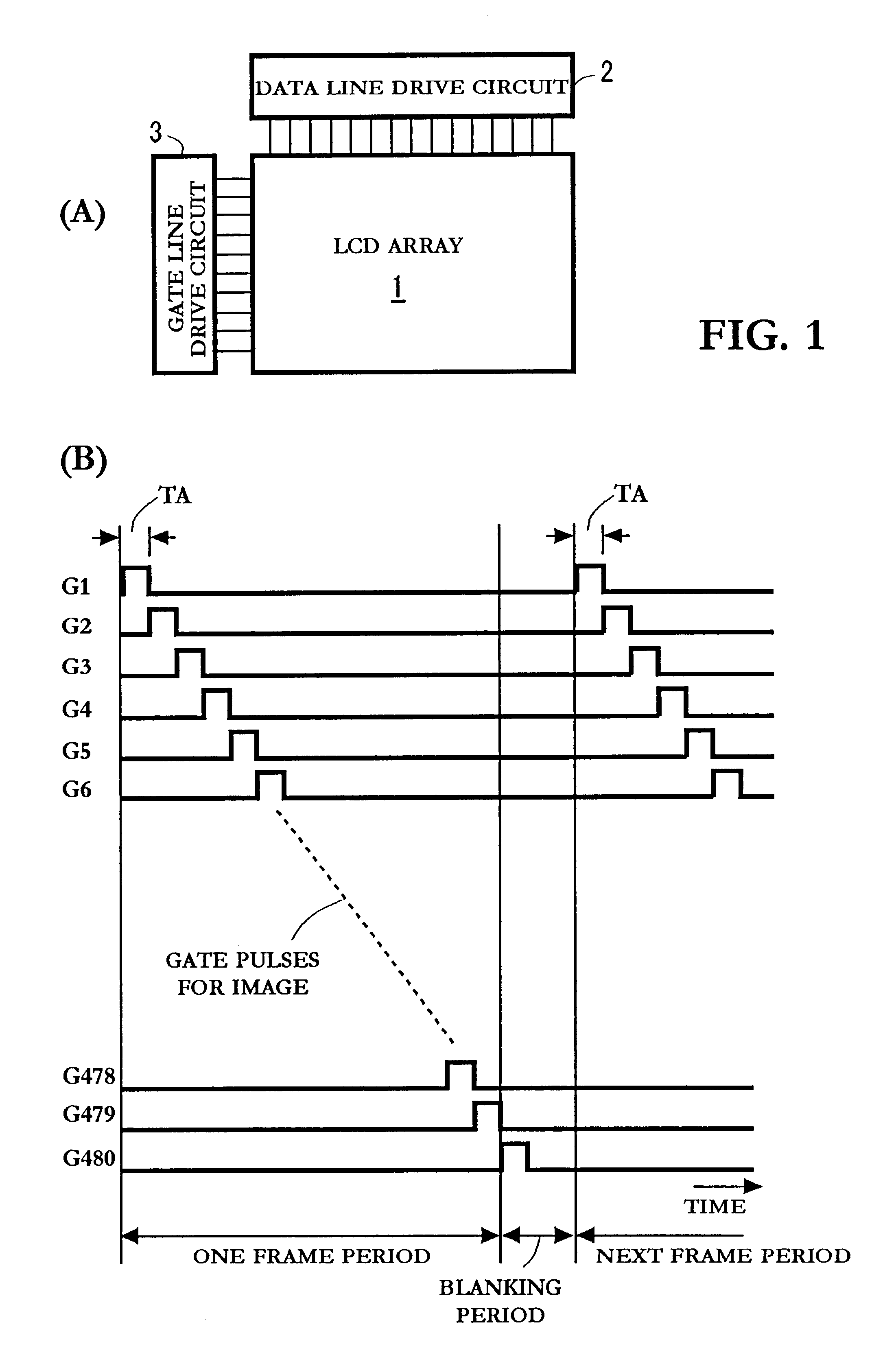
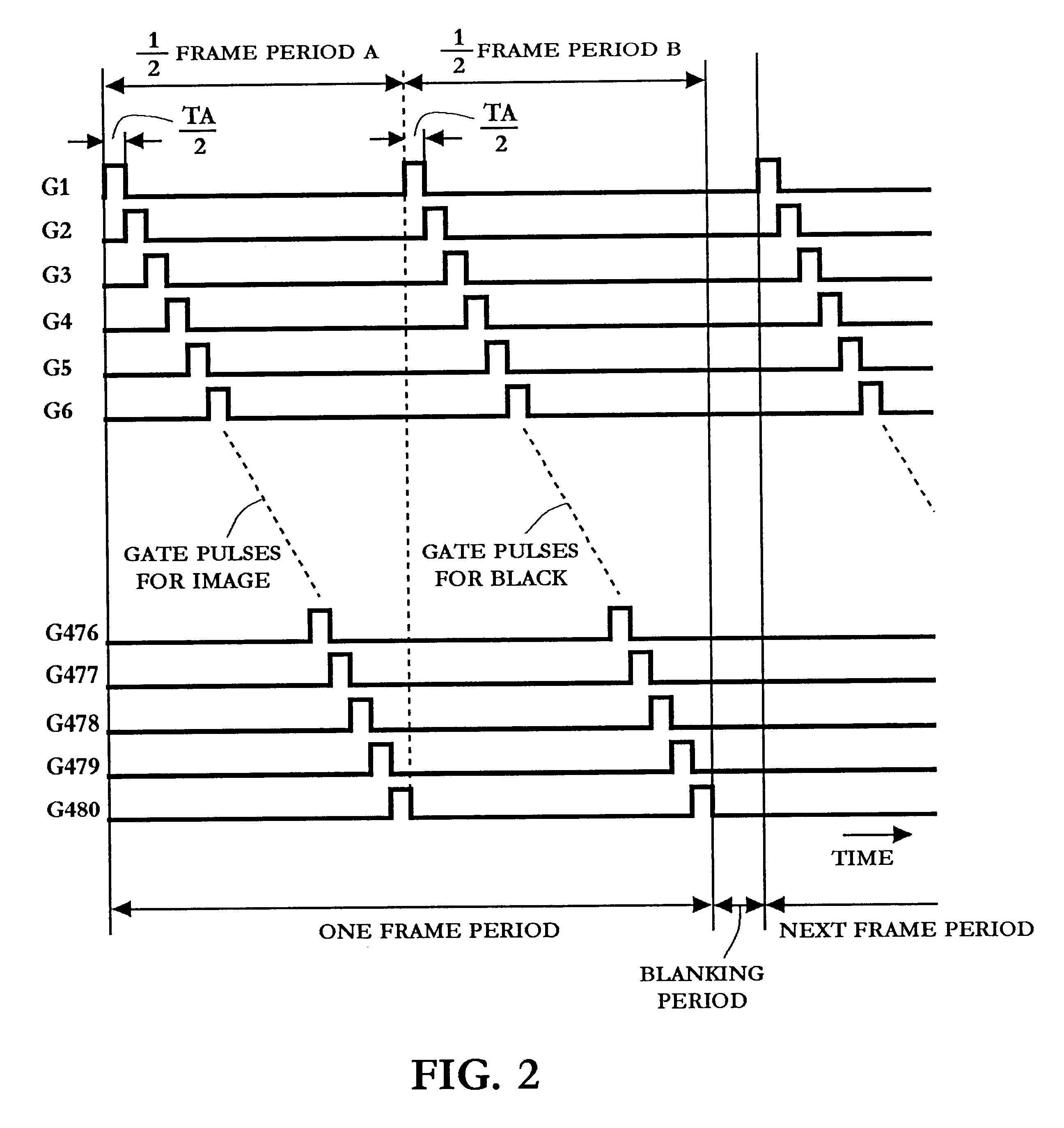
The operation of the present invention is described with reference to FIGS. 7, 8, 9 and 10. The FIGS. 7 and 8 show a timing diagram for writing the image and the full black color for deleting the afterimage into the LCD array. The FIG. 9 shows the gate pulse for writing the image into the LCD array. The FIG. 10 shows the gate pulse for writing the full black color into one pixel, and shows that the black color is written into each pixel three times as a lapse of time. It is noted that the present invention is described by using the LCD array having only 24 pixels in the horizontal direction and 20 pixels in the vertical direction for simplifying the description and the drawings, as stated before, and hence, the number Y of pixel lines or gate lines is 20 in this case.

The write operation for an odd frame period and an even frame period is shown in the FIGS. 7 and 8. A blanking period having even time period periods T.sub.B1 through T.sub.BE, such as four time periods T.sub.B1 through...

second embodiment

Since the black color is continuously written in the pixel lines during the blanking period in the second embodiment, the gate line related to the pixel line, into which the image is supplied, and the gate line(s) related to the pixel lines, into which the black color is supplied, at a selected time period T.sub.N of the odd or even frame period, are defined by the following equation. In the exemplary embodiment using the 20 gate lines, the number of gate lines Y=20, and the number N is 1 through Y (=20). The "n" represents the number of time periods included in the blanking period. In the exemplary embodiment, n=5. Further, the actual gate lines G1 through G20 are considered to be followed by five virtual gate lines G21 through G25, which are equal to the number "n". That is, the number of gate lines considered in this case is (Y+n), i.e. 25 gate lines. And, the virtual gate line G(Y+n+1), i.e. G26, is treated as the gate line G1 of the display surface of the LCD array.

During the t...


PUM


Abstract

To prevent the display image from becoming unclear due to an overlap of the afterimage of the display image of the preceding frame period with the display image of the current frame period so that the image quality of the motion picture may be improved, a display apparatus includes a display surface having a plurality of pixel lines and a write circuit adapted to sequentially write an image into each of said plurality of pixel lines. The write circuit writes, during a time period for writing said image into at least one pixel line, a black color into another pixel line. The another pixel line is separated from the at least one pixel line by a predetermined distance. The write circuit writes the black color into a plurality of pixel lines separated from the at least one gate line by the predetermined distance.

Description

1. Field of the InventionThe present invention relates to a display apparatus, such as a liquid crystal display (LCD) device, a plasma display device, a field emission display device, with a high response speed which can prevent the display image from becoming unclear due to an overlap of the afterimage of the display image of the preceding frame period with the display image of the current frame period to improve the image quality of the motion picture.2. Discussion of the Related ArtThe LCD device with the high response speed, such as a Bend-mode LCD device well known in the art, has been used for improving the image quality of the motion picture in which the displayed image is changed at a high speed. Describing problems in the high response speed LCD device with reference to FIGS. 1(A) and (B), the FIG. 1(A) shows a schematic configuration of a prior LCD device, which includes a LCD array 1, a data line drive circuit 2 and a gate line drive circuit 3. For example, the LCD array ...

Claims


Application Information

Patent Timeline
IPC IPC(8): G09G3/36G02F1/133G09G3/20
CPCG09G3/3648G09G2310/0251G09G2310/061G09G2320/0261
Inventor TAKENAKA, ATSUSHIIKEZAKI, MITSURU
Owner VIDEOCON GLOBAL
Why Eureka
Try Eureka