Cassette and detecting device for installation thereof

Inactive Publication Date: 2002-11-26
BROTHER KOGYO KK
View PDF13 Cites 145 Cited by
  • Summary
  • Abstract
  • Description
  • Claims
  • Application Information

AI Technical Summary

Problems solved by technology

However, in the conventional cassette installation detecting device, a signal to announce the completion of the cassette installation may be produced if the detector surface coincides with the detector portion by accident, even when the cassette is tilted to the right/left or up/down, because the detector surface is provide

Method used


Image

  • Cassette and detecting device for installation thereof
  • Cassette and detecting device for installation thereof
  • Cassette and detecting device for installation thereof

Examples


second embodiment

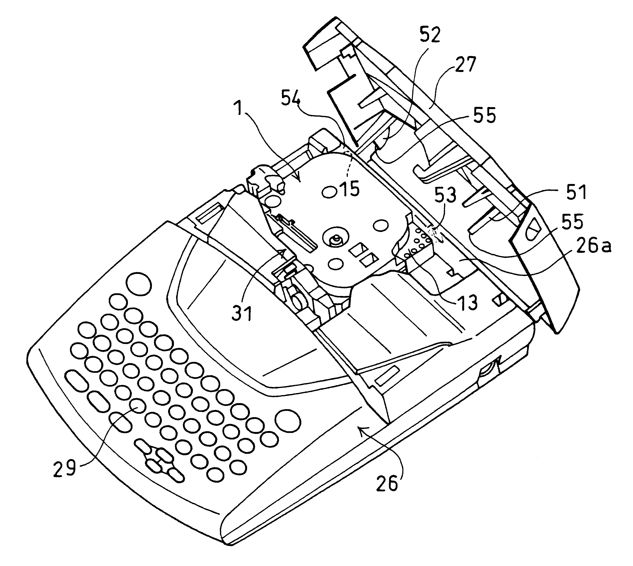
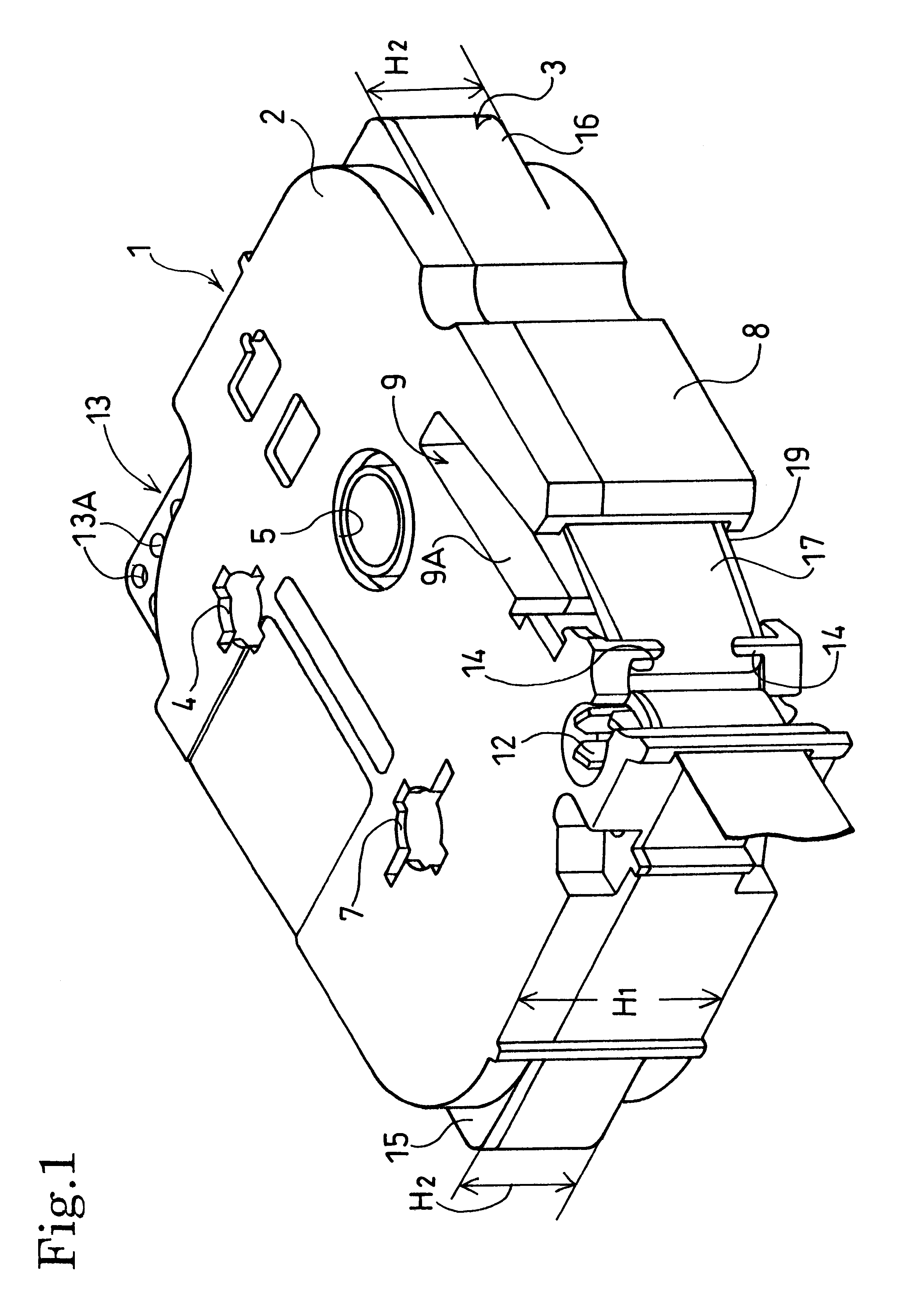
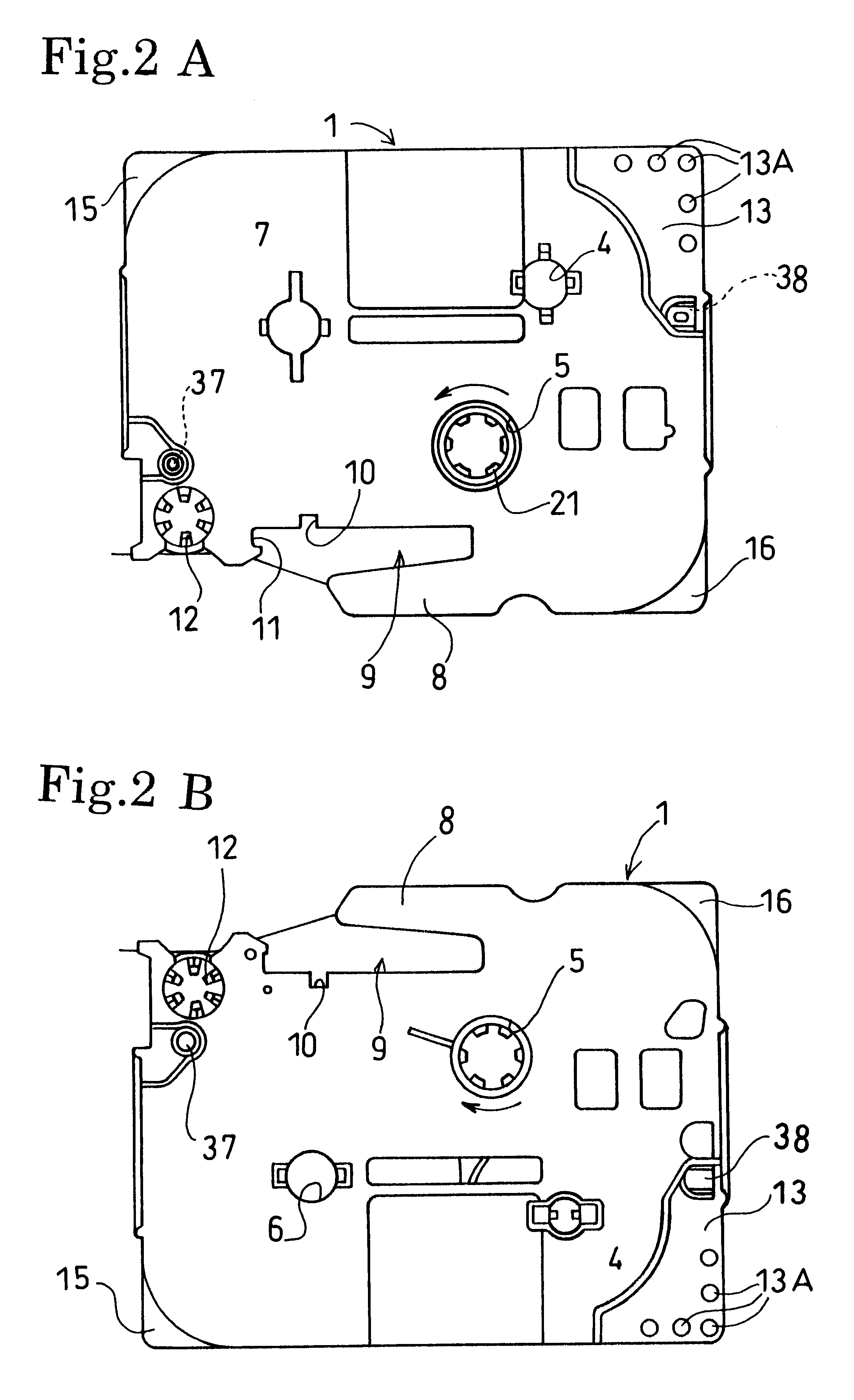
First, the cassette installation detecting device will be described FIGS. 15 through 18.

A cover 127 covers and uncovers a cassette accommodating portion 131 at the upper portion of the cassette accommodating portion 131 by rotating about hole 128A, 128B as a center of rotation. A first pressing member 151, a second pressing member 152, and a third pressing member 153 protrude downward from the inner surface of the cover 127. The first pressing member 151, the second pressing member 152, and the third pressing member 153 are integrally formed with the cover 127 made from, for example, synthetic resin.

first embodiment

As is the case with the first embodiment, the first pressing member 151 is disposed at the position where the first pressing member 151 can press downward the upper surface of the first detector portion 13 of the cassette 1 installed in the cassette accommodating portion 131 when the cover 127 is completely closed and covers the upper portion of the cassette accommodating portion 131. Likewise, the second pressing member 152 is disposed at the position where the second pressing member 152 can press downward the upper surface of the second detector portion 15 of the cassette 1. The third pressing member 153 is disposed at the position where the third pressing member 153 can press downward the upper surface of a third detector portion 115 of the cassette 1. The first pressing member 151, the second pressing member 152 and the third pressing member 153 each have a pressing portion having a flat surface at their lower end surfaces.

A cassette pressing member 154 is provided to the inner ...

third embodiment

Next, the cassette installation detecting device will be described.

A cover 227 covers and uncovers a cassette accommodating portion 231 at the upper portion of the cassette accommodating portion 231 by rotating about rotating portions 228A, 228B as a center of rotation. The cover 227 is made, for example, from synthetic resin. A first pressing member 251, a second pressing member 252, a third pressing member 253, and a fourth pressing member 254 protrude downward from the inner surface of the cover 227.

The first pressing member 251 and the second pressing member 252 are directly fixed to the inner surface of the cover 227. The third pressing member 253 and the fourth pressing member 254 are provided to the inner surface of the cover 227 via a pressing plate 255.

The pressing plate 255 is pivotally supported at its end portion 256 on the inner surface of the cover 227 so that the pressing plate 255 can be pivotally movable at the end portion 256. The pressing plate 255 is urged by a ...


PUM


Abstract

A cassette accommodating portion having an upper open structure is provided on a rear side of a body case in a label tape forming device. A first pressing member and a second pressing member protrude downward from right and left of the inner surface of a cover having a center of rotation at the rear side of the body case. A fin-shaped first detector portion and a fin-shaped second detector portion are formed on right and left of the rear side of a cassette to be installed. When the cassette is installed in the cassette accommodating portion in a proper posture and the cover is closed, the first detector portion and the second detector portion are pressed by the first pressing member and the second pressing member, respectively, and thus the cover is completely closed.

Description

1. Field of the InventionThe invention relates to a label tape forming device that prints indicia onto a tape-shaped recording medium, and to a cassette and a cassette installation detecting device capable of detecting whether the cassette is installed in a proper position in the label tape forming device.2. Description of the Related ArtAs disclosed in Japanese Laid-Open Patent Publication No. 7-68814, Japanese Laid-Open Patent Publication No. 7-314866, and Japanese Laid-Open Patent Publication No. 8-118738, this type of conventional label tape forming device generally includes a cassette accommodating portion having an upper open structure in which a cassette that accommodates a recording medium, such as a printing tape (film tape), and an ink ribbon in a wound state can be accommodated. A plurality of switch holes as a detector surface are formed in a corner of one side of the cassette surface so that a type of the cassette can be detected. That is, the switch holes are arranged ...

Claims


Application Information

Patent Timeline
IPC IPC(8): B41J15/04B41J32/00B41J3/407
CPCB41J3/4075B41J15/044B41J32/00
Inventor TAKAHASHI, TOSHIHIRO
Owner BROTHER KOGYO KK
Why Eureka
Try Eureka