Method for detecting malfunction in clamping and machine tool

a technology of malfunction detection and clamping, applied in the direction of instruments, ignition automatic control, electric controllers, etc., can solve the problems of clamp malfunction, grinding failure, grinding failure, etc., and achieve the effect of precisely and easily detecting any malfunction in clamping a work and accurately and easily detecting any malfunction in clamping

Active Publication Date: 2008-12-09
KOMATSU NTC LTD
View PDF7 Cites 0 Cited by
  • Summary
  • Abstract
  • Description
  • Claims
  • Application Information

AI Technical Summary

Benefits of technology

[0006]In the light of the current condition explained above, an object of the present invention is to provide a clamping malfunction detection method which allows accurate and simple detection of malfunction in clamping a work, and a machine tool performing the same.
[0048]According to the second aspect of the invention, a work is clamped at its both ends with the clamp mechanisms of the respective headstocks while performing servo control on the servomotors of the both headstocks, and at this point, any clamping malfunction is determined when the current or torque generated within the servomotor of either of the headstock is equal to or larger than a predetermined value. Accordingly, the clamping malfunction is easily and precisely detected at the time of clamping the work.
[0049]According to the machine tool of the third aspect of the invention, it becomes possible to precisely and easily detect any malfunction in clamping a work by performing the clamp malfunction detection method according to the first aspect of the invention. Thus, the grinding failure due to the clamping malfunction is effectively prevented before it happens.
[0050]The machine tool according to the fourth aspect of the invention, it becomes possible to precisely and easily detect any malfunction in clamping of a work at the time of clamping the work by performing the clamp malfunction detection method according to the second aspect of the invention. Thus, the grinding failure due to the clamping malfunction is effectively prevented before it happens.

Problems solved by technology

However, when there is abnormality in the driving mechanism of the chuck pawl, such as poor functioning of chuck pawl due to chips entering into sliding sections of the chucking pawls, the chuck pawl does not clamp the work at a predetermined clamping force although the pressure of the operation fluid supplied to the chuck cylinder is normal.
If the grinding operation starts in this state, the work may slip in the chuck due to grinding force, thereby to cause a grinding failure.
Furthermore, when the chucking pawls are used while in a state that they have contaminants adhered thereon, or in a worn-out state, similarly, the work may slip to cause a grinding failure.
That is, the detection of only the pressure of the hydraulic oil supplied to the chuck cylinder may not always detect clamp malfunction.

Method used


Image

  • Method for detecting malfunction in clamping and machine tool
  • Method for detecting malfunction in clamping and machine tool
  • Method for detecting malfunction in clamping and machine tool

Examples


embodiments

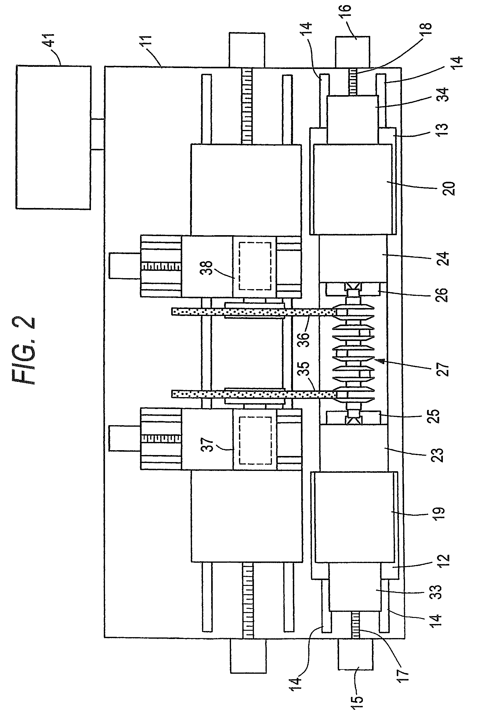
[0057]The invention is hereinafter described according to one embodiment with reference to FIGS. 1 trough 4, which is embodied as a grinding machine for crankshafts. As seen in FIG. 2 which is a plane view of the grinding machine, over a top surface of a bed 11, a left-and-right pair of tables 12 and 13 are provided so as to be independently movable back and forth in the same direction over rails 14 that are laid down in parallel in a horizontal direction. On the left and right ends of the bed 11, table carrier motors 15 and 16 are provided, which are configured to move the tables 12 and 13 back and forth by feed screws 17 and 18.

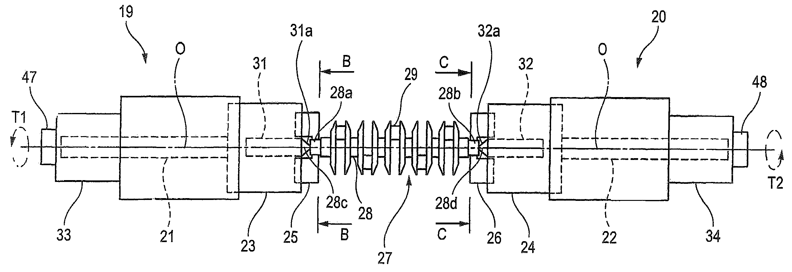
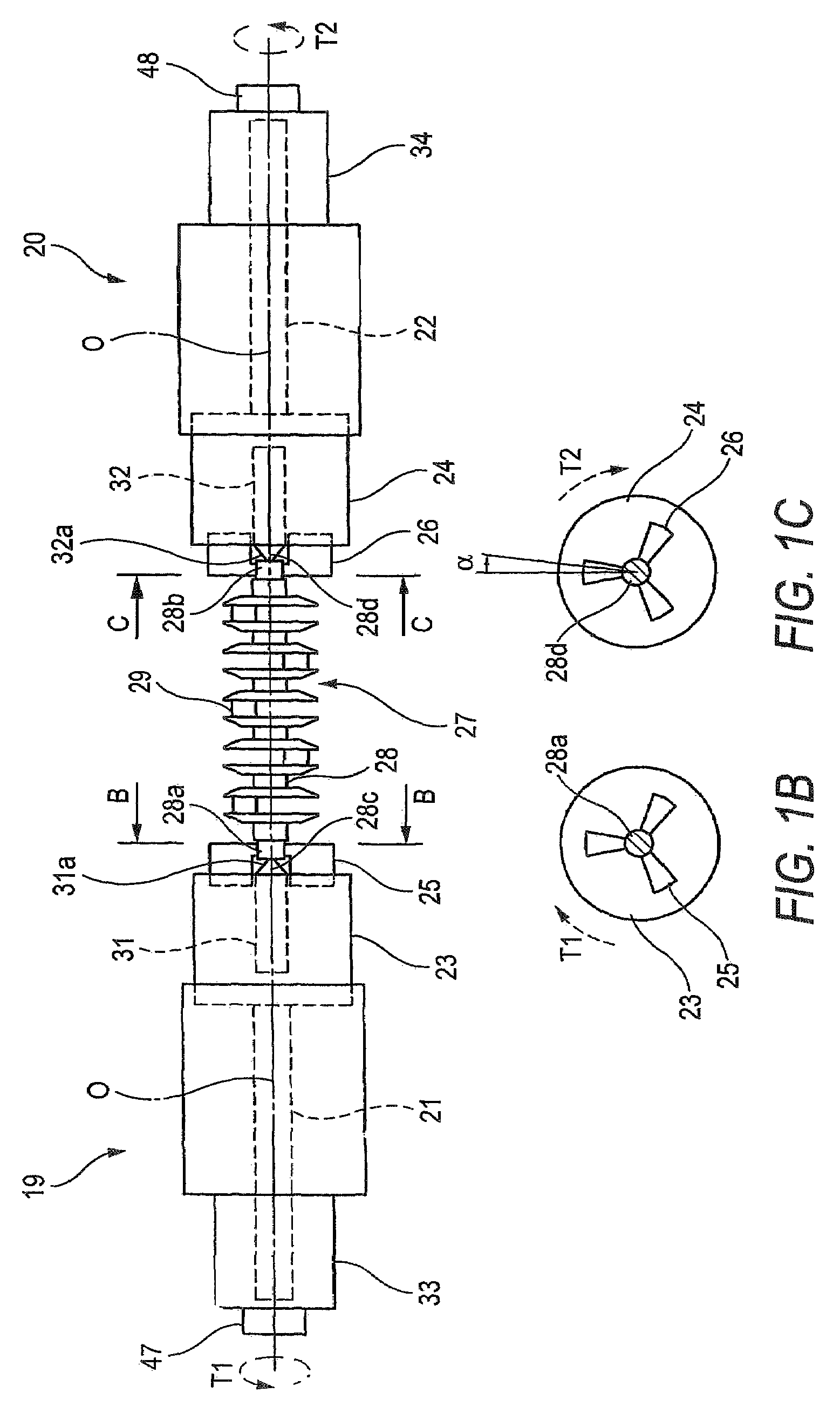
[0058]Over the top surfaces of the tables 12 and 13, a first headstock 19 and a second head stock 20 are provided, and to their first and second main spindles, as shown in FIGS. 1A to 1C, first and second clamping mechanisms 23 and 24 are attached. To the first and second clamping mechanisms 23 and 24, first and second hydraulic chucks 25 and 26 are provide...


PUM

PropertyMeasurementUnit
torqueaaaaaaaaaa
shapeaaaaaaaaaa
pressureaaaaaaaaaa

Abstract

The method for detecting any clamping malfunction of the work within the machine tool which clamps both ends of the work with clamping mechanisms 23, 24 of a pair of headstocks 19, 29, and processes the work by spinning the work through synchronous rotation of main spindles 21, 22 of the pair of headstocks by servomotors 33, 34, wherein, after clamping the both ends of the work 27 with the clamping mechanisms 23, 24 of the respective headstocks 19, 20, and while both the servomotors 33, 34 of the headstocks are in a servo-ON state, a command for a minute angle α rotation is given to the servomotor 34 of only one of the headstocks, and at this point, any malfunction in clamping is determined when a current or torque generated within the servomotor of one or the other of the headstocks is smaller than a predetermined value.

Description

BACKGROUND OF THE INVENTION[0001]1. Field of the Invention[0002]The present invention relates to a method for detecting a malfunction in clamping a work within a machine tool and a machine tool performing the same.[0003]2. Description of Related Art[0004]In a grinding machine which grinds a work having a relatively elongated shaft-like shape, such as a crankshaft, both ends of a work are clamped by clamping mechanisms provided on a right-and-left pair of head stocks, and the work is machined while synchronously rotating main spindles of the pair of headstocks by servomotors as described in Japanese Patent Unexamined Publication JP-A-2002-239873. The clamping mechanisms use hydraulic chucks which chuck the work from the outer periphery of the work by chucking pawls driven by hydraulic chuck cylinders. The verification whether these clamping mechanisms have or have not properly clamped the work has been performed by using a pressure switch to check whether a specified pressure of oper...

Claims


Application Information

Patent Timeline
Patent Type & Authority Patents(United States)
IPC IPC(8): B23P23/00B23B27/00B23B31/00B23Q17/00B24B5/42B24B19/08B24B41/06
CPCB23Q17/005B24B5/42Y10T82/10Y10T29/5114Y10T409/303752
Inventor AMMI, SADATSUNE
Owner KOMATSU NTC LTD
Why Eureka
Try Eureka