Engine control system and control method thereof

Active Publication Date: 2009-06-04
HITACHI ASTEMO LTD
View PDF5 Cites 64 Cited by
  • Summary
  • Abstract
  • Description
  • Claims
  • Application Information

AI Technical Summary

Benefits of technology

[0006]The present invention has been made in consideration of the problems as described above. An object of the present invention is to provide a system for controlling an engine, which employs EGR, by correctly estimating an EGR rate and the in-cylinder oxygen concentration even in a transitional operating state particularly including the acceleration and deceleration, and even in the case of the engine deterioration.
[0007]In order to solve the above-described problems, the present invention provides an engine control system that includes an EGR flow sensor for directly detecting a flow rate of an EGR gas passing through an EGR path. The engine control system further includes: first EGR rate estimation means for estimating an EGR rate on the basis of an output value of the EGR flow sensor and an output value of an intake airflow sensor; and second EGR rate estimation means for estimating an EGR rate on the basis of the intake pressure and an output value of the EGR flow sensor. Preferably, when an operation state of an engine is a steady state, the engine control is performed on the basis of the result of the estimation by the first EGR rate estimation means. In contrast, when the operation state of the engine is a transient state, the engine control is performed on the basis of the result of the estimation by the second EGR rate estimation means. In addition, the in-cylinder oxygen concentration is calculated from the estimation result of the EGR rate, and each engine parameter is then controlled on the b

Problems solved by technology

To be more specific, the O2 sensor has a problem of the detection responsiveness to a change in oxygen concentration.
At the time of the transient operation such as rapid acceleration and rapid deceleration, it is difficult for the O2 sensor to correctly estimate not only the oxygen concentration in EGR but also the in-cylinder oxygen concentrati

Method used


Image

  • Engine control system and control method thereof
  • Engine control system and control method thereof
  • Engine control system and control method thereof

Examples


first embodiment

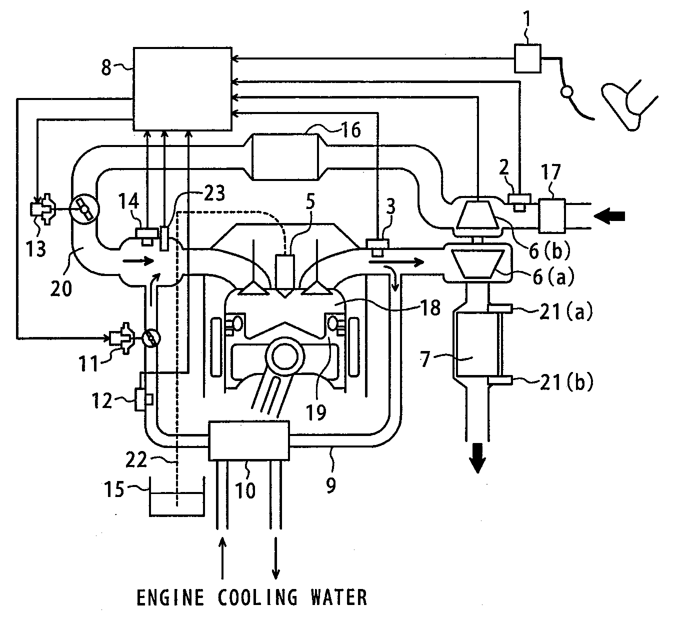
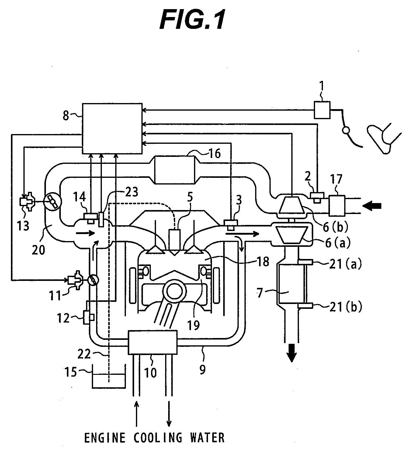
[0024]FIG. 1 is a diagram illustrating the configuration of an engine control system according to the present invention.

[0025]In FIG. 1, reference numeral 19 denotes an engine. Disposed from upstream to downstream with respect to the engine 19 are an air cleaner 17; an airflow sensor 2; a compressor 6(b) of a supercharger; an intercooler 16; a throttle 13 for adjusting the amount of intake air; an intake port 20; and a fuel injection valve (hereinafter referred to as an “injector”) 5. In this embodiment, intake air amount control means is composed of the compressor 6(b), the intercooler 16, and the throttle 13; intake air amount detection means corresponds to the airflow sensor 2. Reference numeral 8 denotes an engine control unit (hereinafter referred to as “ECU”). The ECU 8 determines the combustion mode, control variables, or the like of the engine 19 based on the driver's requests such as for an accelerator opening angle α and braking amount; vehicle states such as the vehicle s...

third embodiment

[0051]FIG. 13 is a diagram illustrating as an example a configuration of an engine control system according to the present invention. In this embodiment, in contrast to the engine configurations described in the above embodiments, the EGR path 9 functions as a flow path that connects between a point after a catalyst 7 in exhaust gas and a compressor 6(b) of the supercharger. In addition, the throttle 13 for adjusting the amount of intake air is located immediately on the downstream side of the air cleaner 17, and at the same time, on the upstream side of an intake-air-side communication entrance of the EGR path 9. In this configuration, an EGR gas which has passed through the catalyst 7 in the exhaust gas can be supplied from the upstream. Therefore, a large amount of EGR gas containing little fouling can be returned to the engine. If this configuration is employed, because the distance to the airflow sensor 2 viewed from the combustion chamber 18 of the engine is substantially the ...


PUM


Abstract

An engine that re-circulates its exhaust gas suffers decreased accuracy in estimating an EGR rate real-time especially while the operating state of the engine is in a transitional state, which often results in torque fluctuations and deteriorated exhaust gas.
A sensor for directly detecting an EGR flow rate is disposed in an EGR path. An EGR rate and in-cylinder oxygen concentration are calculated from the output value of that sensor. In addition, when this EGR rate calculation method is used, the calculation is properly switched between a steady operation state characterized by a low load and small rotational fluctuations and a transitional operating state including the acceleration and deceleration. This makes it possible to correctly estimate the EGR rate and the in-cylinder oxygen concentration under a wide range of engine operation conditions, and thereby to avoid the fluctuation of torque and the deterioration of exhaust gas.

Description

BACKGROUND OF THE INVENTION[0001]1. Field of the Invention[0002]The present invention relates to a control technology and method of an engine equipped with an exhaust gas recirculation (hereinafter referred to as “EGR”) apparatus that returns part of exhaust gas to an intake pipe.[0003]2. Description of the Related Art[0004]In the field of diesel engines, and the like, there is known a technology for concurrently reducing soot and NOx by using the effect of reducing the combustion temperature based on the application of the exhaust gas recirculation (EGR), and the effect of uniformalizing a mixture gas by increasing an ignition delay period. The combustion temperature and the ignition delay period are influenced by the in-pipe inert gas (CO2) concentration and the in-cylinder oxygen concentration that change by the introduction of EGR. Therefore, in order to carry out the engine control, it is important to correctly detect / estimate not only the EGR rate but also the inert gas concen...

Claims


Application Information

Patent Timeline
IPC IPC(8): F02D41/00
CPCF02D41/0002Y02T10/47F02D41/18F02D41/222F02D41/3035F02D41/3076F02D2041/0075F02D2200/0406F02D2400/08F02M25/0707F02M25/0709F02M25/0731F02M25/0754Y02T10/42F02D41/0072F02M26/05F02M26/06F02M26/28F02M26/47Y02T10/40
Inventor YAMAOKA, SHIROSUKEGAWA, YOSHIHIROTOKUYASU, NOBORUHOSHIKA, HIROAKIKASHIO, KAORI
Owner HITACHI ASTEMO LTD
Why Eureka
Try Eureka