Antenna components and manufacturing method therefor

a technology of antenna components and manufacturing methods, applied in the direction of antennas, antenna details, collapsible antennas, etc., can solve the problems of reducing the aesthetic appearance of the antenna, affecting the picture quality, and the prior antennas are not particularly aesthetically appealing, so as to achieve the effect of improving the picture quality

Inactive Publication Date: 2002-11-26
BELLSOUTH INTPROP COR
View PDF25 Cites 19 Cited by
  • Summary
  • Abstract
  • Description
  • Claims
  • Application Information

AI Technical Summary

Benefits of technology

Over the years, many improvements to televisions and devices and methods for transmitting and receiving television signals have been made. In the early days of television, signals were transmitted over terrestrial broadcast networks and received through the use of antennas. Signal strength and quality, however, were often dependent upon the geography of the land between the transmitting antenna and the receiving antenna. Although such transmission methods are still in use today, the use of satellites to transmit television signals is becoming more prevalent. Because satellite transmitted signals are not hampered by hills, trees, mountains, etc. and operate using broader frequency ranges, such signals typically offer the viewer more viewing options and improved picture quality. Thus, companies have found offering satellite television services to be very profitable and, therefore, it is anticipated that more and more satellites will be placed in orbit in the years to come.

Problems solved by technology

Such prior antennas are not particularly aesthetically appealing.
The feed / LNBF assemblies are typically attached to the end of the feed support arm with upstanding posts which can further detract from the antenna's aesthetic appearance.
Furthermore, most antenna reflectors are coupled directly to a mounting bracket that also detracts from the antenna's appearance.

Method used


Image

  • Antenna components and manufacturing method therefor
  • Antenna components and manufacturing method therefor
  • Antenna components and manufacturing method therefor

Examples


Embodiment Construction

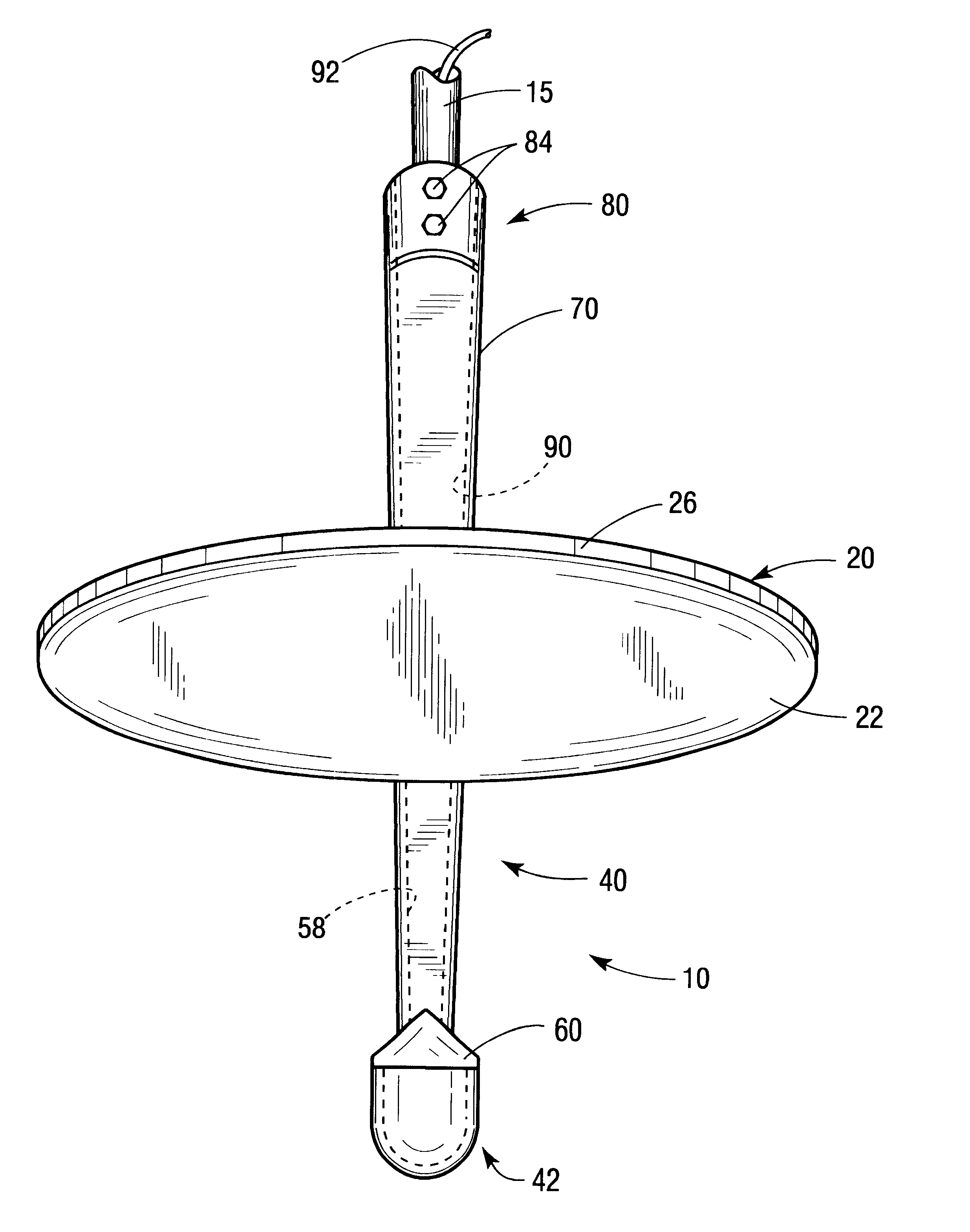
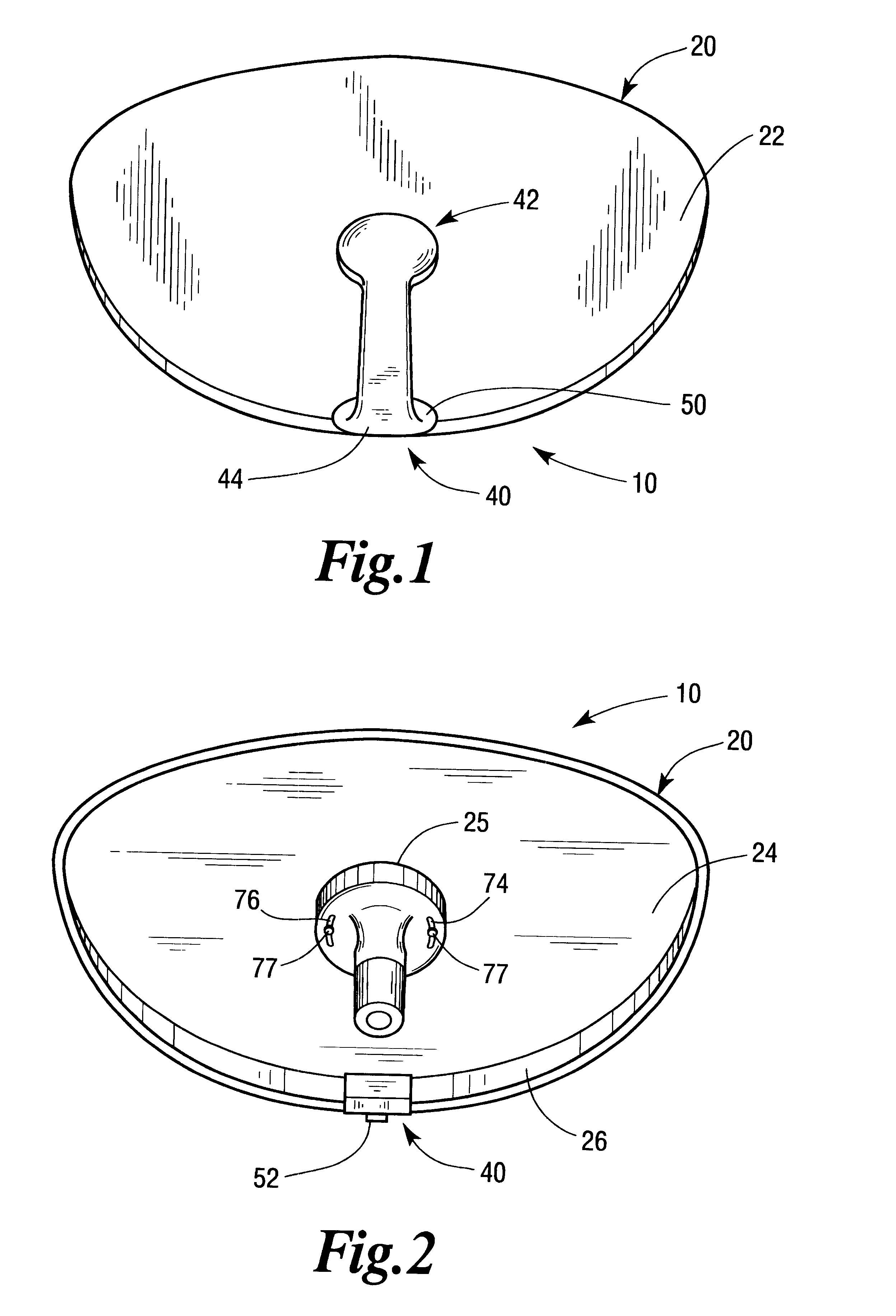
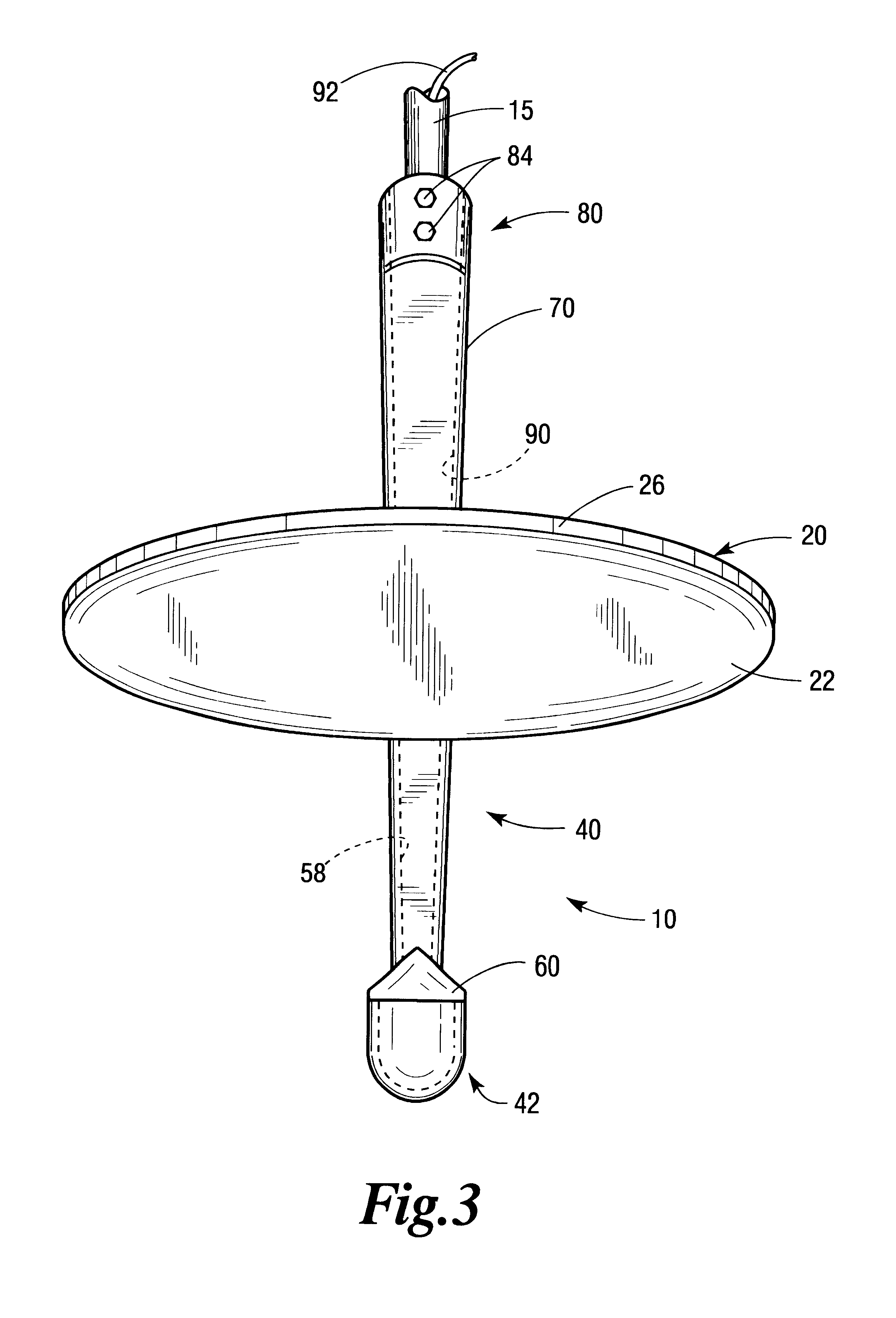
Referring now to the drawings for the purposes of illustrating embodiments of the invention only and not for the purposes of limiting the same, FIGS. 1-5 illustrate an antenna 10 that comprises a parabolic reflector 20, a feed support arm 40 and a reflector mounting arm 70. Reflector 20 may be fabricated from fiberglass-reinforced plastic (a "first material") utilizing conventional thermoset fiberglass compression or injection molding processes. In the alternative, the reflector may be manufactured from stamped metal (i.e., steel, aluminum, etc.).

As can be seen in FIGS. 1, 3, and 5, the reflector 20 has a front surface 22 and a rear surface 24. A rim member 26 is molded around the perimeter of the reflector and protrudes from the rear surface 24 thereof. As shown in FIG. 6, a notch 30 ("point of attachment") is provided in the perimeter of the reflector 20 at the bottom thereof for attaching the forwardly extending portion of the support arm in the manner described in further detail...


PUM


Abstract

A support arm arrangement or assembly for a satellite antenna and manufacturing method therefor. In one embodiment, the support arm arrangement includes a hollow support arm having a front end and a real attachment end is affixed to the antenna reflector adjacent is perimeter. A mounting arm may be attached to the rear surface of the reflector or, in another embodiment, the mounting arm comprises an integral portion of the support arm. A feed / LNBF assembly is supported with the front end of the support arm. The feed / LNBF assembly may be electronically coupled to a set top box by a cable that is passed through the hollow support arm and the hollow mounting arm. Methods of constructing support arm assemblies for satellite antennas are also disclosed.

Description

Not applicable.FEDERALLY SPONSORED RESEARCHNot applicable.1. Field of the InventionThe subject invention relates to satellite antennas and methods of manufacturing satellite antennas and their components.2. Description of the Invention BackgroundThe advent of the television can be traced as far back to the end of the nineteenth century and beginning of the twentieth century. However, it wasn't until 1923 and 1924, when Vladimir Kosma Zworkykin invented the iconoscope, a device that permitted pictures to be electronically broken down into hundreds of thousands of components for transmission, and the kinescope, a television signal receiver, did the concept of television become a reality. Zworkykin continued to improve those early inventions and television was reportedly first showcased to the world at the 1939 World's Fair in New York, where regular broadcasting began.Over the years, many improvements to televisions and devices and methods for transmitting and receiving television sig...

Claims


Application Information

Patent Timeline
Patent Type & Authority Patents(United States)
IPC IPC(8): H01Q19/13H01Q19/10
CPCH01Q19/13
Inventor WEAVER, TIMOTHY H.
Owner BELLSOUTH INTPROP COR
Why Eureka
Try Eureka