Imaging arrangement which allows for capturing an image of a view at different resolutions

a technology of image arrangement and resolution, applied in the field of image arrangement, can solve the problem of limited detail of the portion of the image which is visible, and achieve the effect of improving the quality of the imag

Inactive Publication Date: 2002-12-10
CEDAR LANE TECH INC +1
View PDF157 Cites 172 Cited by
  • Summary
  • Abstract
  • Description
  • Claims
  • Application Information

AI Technical Summary

Problems solved by technology

When such an area is enlarged, detail of the portion of the image which is visible is usually limited because of the resolution at which the image is digitized.

Method used


Image

  • Imaging arrangement which allows for capturing an image of a view at different resolutions
  • Imaging arrangement which allows for capturing an image of a view at different resolutions
  • Imaging arrangement which allows for capturing an image of a view at different resolutions

Examples


Embodiment Construction

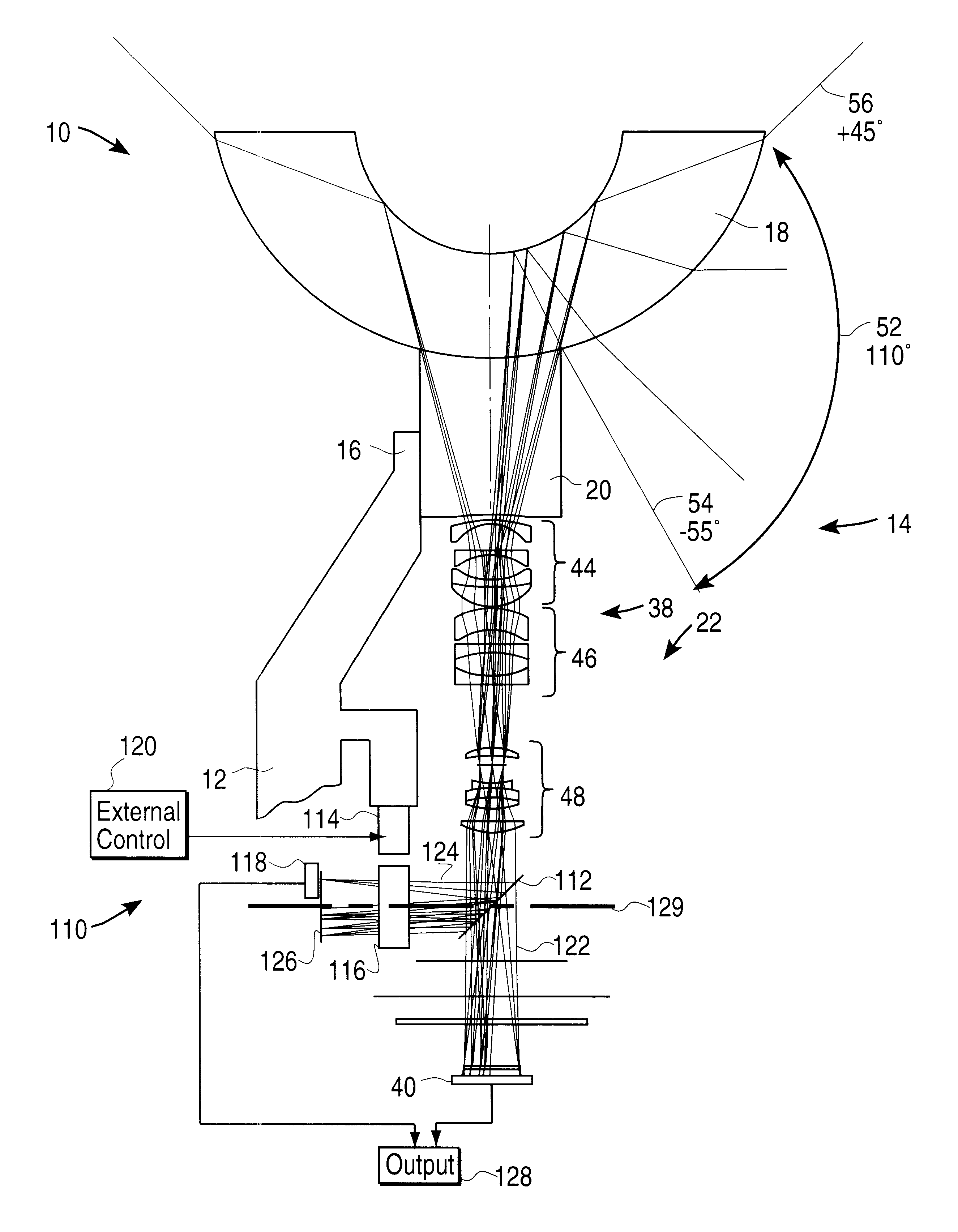
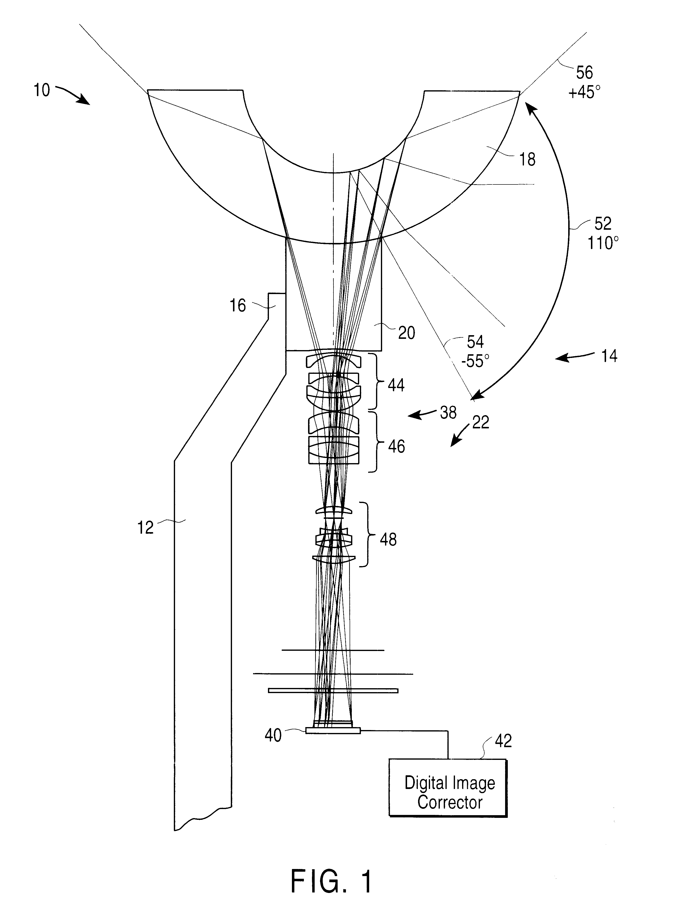
FIG. 1 of the accompanying drawings illustrates apparatus 10, according to an embodiment of the invention, for capturing a panoramic scene. The apparatus 10 includes a vertically extending support structure 12, and a panoramic imaging arrangement 14 which is secured to an upper end 16 of the support structure 12.

The support structure 12 may be any device having an upper end 16 which is high enough for purposes of providing a viewpoint of a panoramic scene. The support structure 12 is typically part of a housing for the panoramic imaging arrangement 14 and may, for example, include a vertically extending post, a tripod stand, or part of building structure.

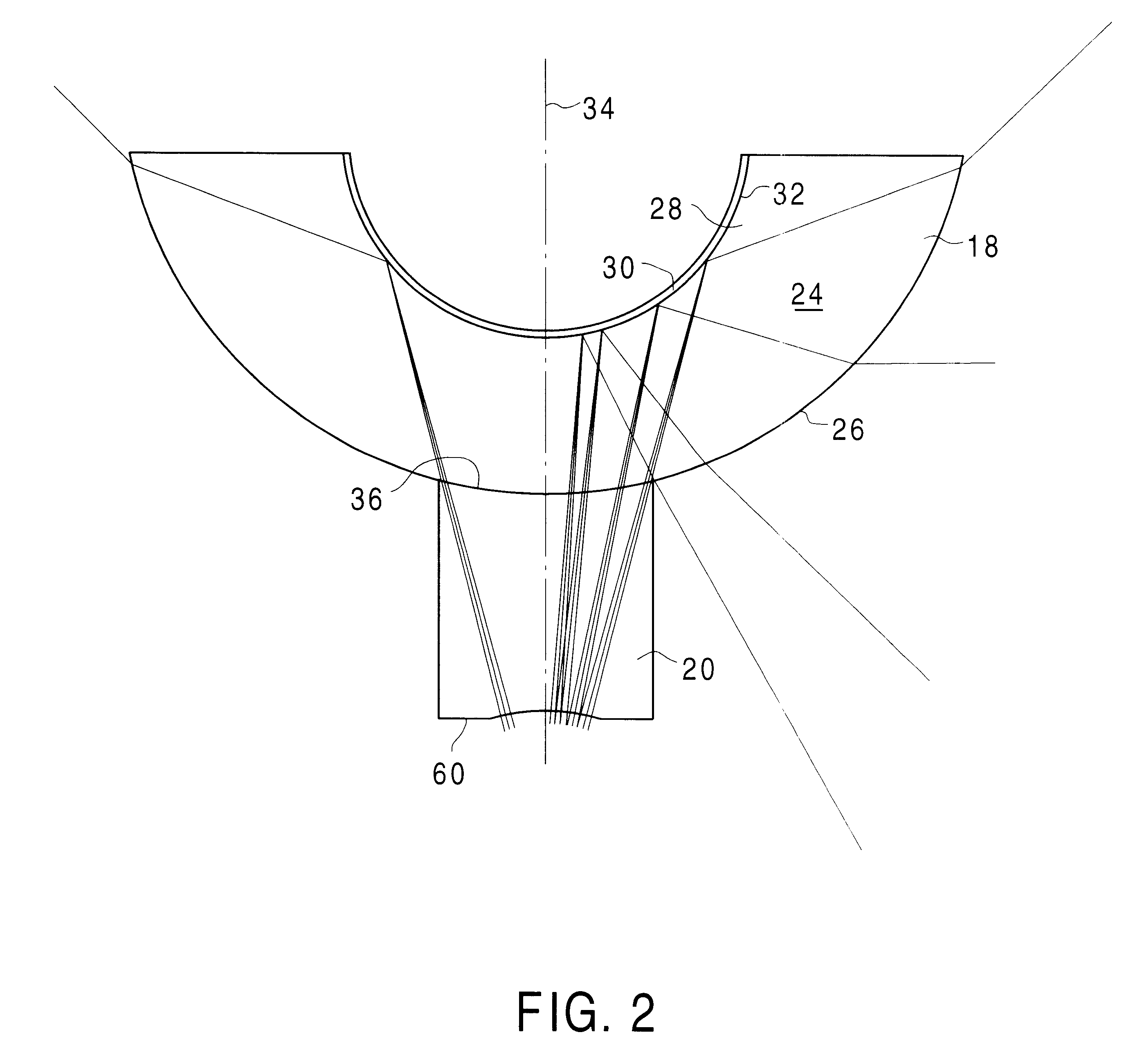
The panoramic imaging arrangement 14 includes a first, upper lens block 18, a second, lower lens block 20, and apparatus 22, positioned below the second lens block 20, for manipulating light so as to correct certain aberrations of the light and to focus the light (hereinafter generally referred to as the "light manipulation apparatu...


PUM


Abstract

The invention provides a method of viewing an image. Light is projected from the image. The projected light is split into first and second bundles of light focusing over a first and a second focal region respectively. The light at the first focal region is detected at a first resolution. The light at the second focal region is detected at a second resolution different from the first resolution.

Description

1). Field of the InventionThis invention relates to a imaging arrangement of the kind capable of capturing light received from a scene, and to a method of capturing an image of a scene, in particular at different resolutions.2). Discussion of Related ArtPanoramic imaging arrangements have become popular in recent years for purposes of viewing 360.degree. surrounding panoramic scenes. Older generations of panoramic imaging arrangements generally consisted of revolving periscope-like constructions having relatively complex mechanisms for revolving them. More recently, stationary panoramic imaging arrangements have been developed. A stationary panoramic imaging arrangement generally has one or more lenses, each having a vertically extending axis of revolution, which are used to refract or reflect light received from a 360.degree. surrounding panoramic scene. The lenses alter the direction of the light, whereafter the light passes through a series of lenses which are located vertically ...

Claims


Application Information

Patent Timeline
Patent Type & Authority Patents(United States)
IPC IPC(8): G02B13/06G02B17/08G03B37/00H04N7/18H04N5/262G02B27/14
CPCG02B13/06G02B27/1066G02B27/123G02B27/143G02B27/144G03B37/00G08B13/19626G08B13/1963H04N5/2628H04N7/183
Inventor WALLERSTEIN, EDWARD P.DRISCOLL, JR., EDWARDLOMAX, WILLARD CURTIS
Owner CEDAR LANE TECH INC
Why Eureka
Try Eureka