
Compact panel lifter

a panel and compact technology, applied in the field of panel lifting devices, can solve the problems of not holding a panel in place for securing, injury to the operator, not allowing the panel to be placed laterally, etc., and achieve the effects of improving back hygiene, compact, safe and ergonomic, and convenient us

Inactive Publication Date: 2002-12-24
NELSON MARK S
View PDF6 Cites 22 Cited by
  • Summary
  • Abstract
  • Description
  • Claims
  • Application Information

AI Technical Summary

Benefits of technology

Thus the reader will see that this invention creates a simple, economical, compact, safe, and ergonomic lifting device. This unit not only is highly functional, but has the potential for improving back hygiene and reducing hand injuries related to installation of construction panels. There is also inherent safety in the fact that the operator does not have to stand on the unit while at the same time trying to adjust and secure a panel.

Problems solved by technology

The disadvantage of these devices is that they do not hold a panel in place for securing.
This can cause injury to the operator due to imprecise nature of the devices and imprecision of placement of the panel.
A door transporting and mounting machine in U.S. Pat. No. 4,820,151 to Shern, Mar. 7, 1989 will lift and place a panel against a wall but will not allow for placing the panel laterally flush against an adjacent panel.
One disadvantage is that the panel must first be lifted into the device.
It also lacks simplicity, low cost of construction and purchase, relative ease of operation, and hands free operation.
A ceiling panel lifting device in U.S. Pat. No. 3,828,942 to Young, Aug. 13, 1974 can be used to lift and hold panels in a vertical position but lacks simplicity, low cost of construction and purchase, relative ease of operation, and hands free operation.
all function only to lift and hold panels against a horizontal ceiling and are not suitable for use in vertically lifting and holding a panel against a vertical wall.

Method used


Image

  • Compact panel lifter
  • Compact panel lifter
  • Compact panel lifter

Examples


Embodiment Construction

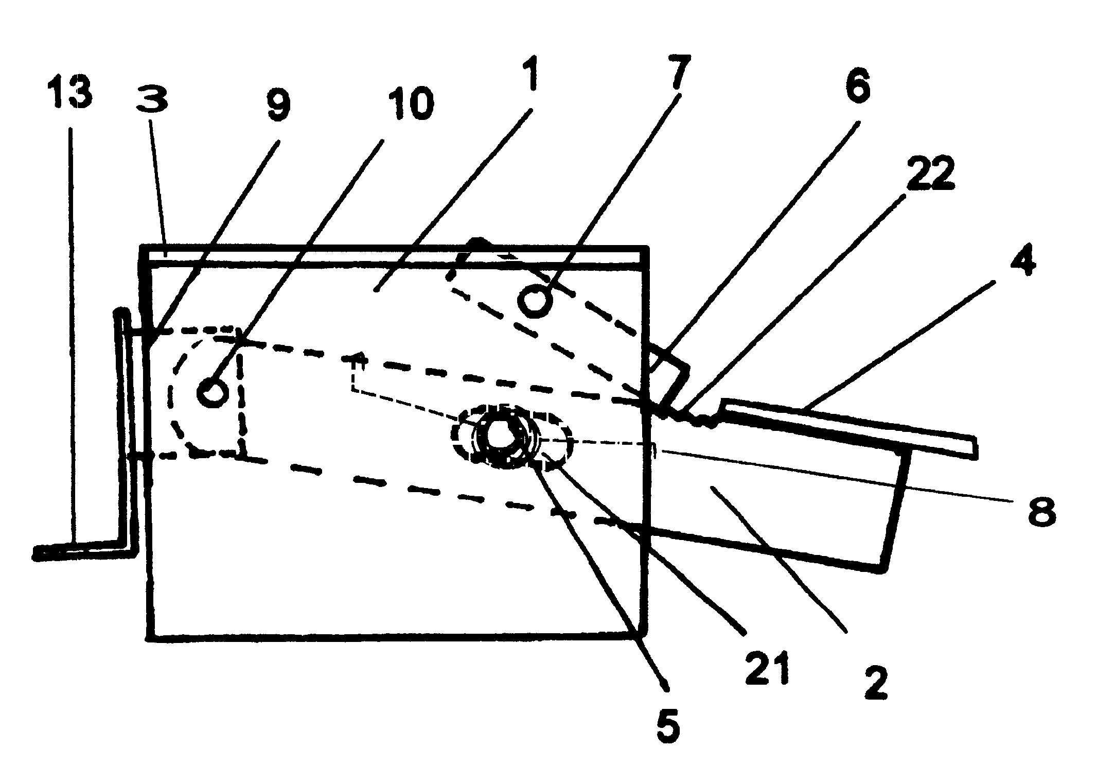
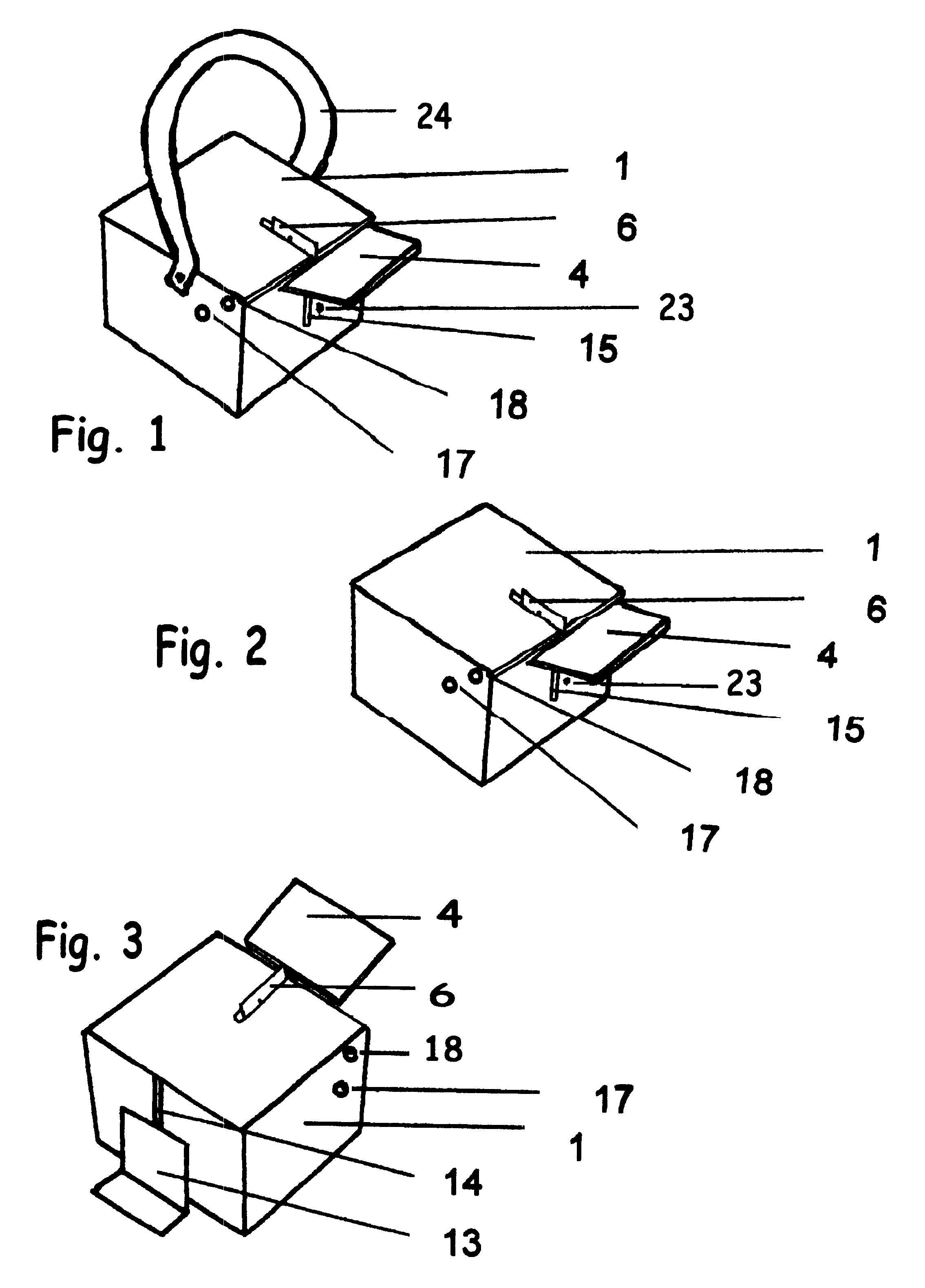
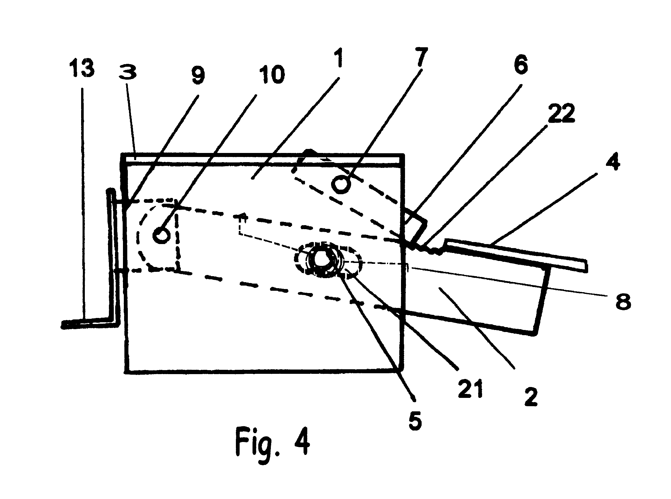
A preferred embodiment of the present invention is illustrated in FIGS. 1, 2, and 3.

A body 1 as shown in FIGS. 1, 2, 3, and 4 may be produced from materials such as 11 to 14 gauge 4.times.4 inch tubular steel (preferred), plastic, or composite. Into the body are cut 2 vertical slots 14 and 15 which serve as travel guides for a lever arm 2, tab 9, and locking arm 6. One slot should be offset to the left or right of the other by the thickness of the lever arm 2. This is to allow for the necessary overlap of the lever arm 2 on the tab 9. The slot width should be just slightly larger than the width of the lever arm 2, tab 9, and locking arm 6 so as to allow for easy unimpeded travel of these parts. A lever arm bolt hole 17 is made in both sides of the body 1 to accept the lever arm bolt 5. The exact position is variable and different positions can be used to obtain different lifting ratios and front to back travel distances of the lever arm 2. A locking arm bolt 18 hole is made in both ...


PUM


Abstract

A simple, compact, hands free device that allows a single operator to vertically lift and hold construction panels to a desired height for securing to a wall surface. Downward foot pressure on one end of a slotted lever arm causes a panel lifting surface on the other end of the lever arm to rise. This lever arm is supported by a base support which also supports a locking arm. Once the desired height is reached, the device locks the panel into position. The operator is then free to move about, adjust, and finally secure the panel. Once the panel is secured, the locking arm is released by simple forward pressure. With the aid of a foot strap, the device can then be transported to the next panel ready for lifting. This device eliminates the use of hands, bending, or stooping during the process of lifting construction panels.

Description

Not applicableThis invention was not conceived or produced with the aid of any federally sponsored research or development.1. Field of InventionThis invention relates to a panel lifting device, specifically a simple, inexpensive, hands free device designed to vertically lift and hold construction panels in place for adjusting and securing.2. Description of Prior ArtOriginally devices used for lifting construction panels have included such things as a simple block and pry bar or automobile leaf spring that the installer must stand on. The disadvantage of these devices is that they do not hold a panel in place for securing. Also, the operator must pry and hold with hand or foot at the same time they are adjusting and finally securing the panel. This can cause injury to the operator due to imprecise nature of the devices and imprecision of placement of the panel.A door transporting and mounting machine in U.S. Pat. No. 4,820,151 to Shern, Mar. 7, 1989 will lift and place a panel agains...

Claims


Application Information

Patent Timeline
IPC IPC(8): B66F15/00
CPCB66F15/00Y10S269/905
Inventor NELSON, MARK S.
Owner NELSON MARK S
Learn More