Downstroke sucker rod pump and method of use

a sucker rod and sucker rod technology, which is applied in the direction of positive displacement liquid engines, liquid fuel engines, borehole/well accessories, etc., can solve the problems of waste of energy, waste of energy from the weight of rods and plunger assemblies on the downstroke, and insufficient utilization of energy, so as to reduce the electrical cost per barrel

Inactive Publication Date: 2002-12-24
SKILLMAN MILTON
View PDF18 Cites 26 Cited by
  • Summary
  • Abstract
  • Description
  • Claims
  • Application Information

AI Technical Summary

Benefits of technology

One of the major advantages of the pumping apparatus of the present invention is the utilization of the normally wasted energy associated with downward movement of the reciprocating pump plunger and the string of rods attached to the reciprocating pump plunger to force fluids to the surface of the well during the downstroke and the fact that the only energy required during the upstroke is energy required for lifting the string of rods and the reciprocating pump plunger. If the power unit is powered by an electrical motor, the motor draws essentially the same amperage on the upstroke as the downstroke, resulting in an approximately 50% reduction in electrical cost per barrel of produced fluid.

Problems solved by technology

This requires a great deal of energy.
Thus the lifting of great weights on the upstroke requires a great amount of energy while the energy from the weight of the rods and plunger assembly on the downstroke is wasted and not utilized.
The great difference between the load on an upstroke and the lack of load on a downstroke creates a counterbalance problem on the power unit.
This great difference in weight cannot be fully counterbalanced.
Another problem with lift pumps of the prior art is associated with stretching of the rods by which the plunger and fluids are lifted in the production string.
This results in loss of movement or plunger travel as compared to the length of movement of the power unit stroke.
This results in inefficiency.
Although this pumping apparatus appears to utilize the weight of the rods in response to gravity as a source of pumping energy for pumping on the downstroke, it does not substantially reduce the energy required on the upstroke.

Method used


Image

  • Downstroke sucker rod pump and method of use
  • Downstroke sucker rod pump and method of use
  • Downstroke sucker rod pump and method of use

Examples


Embodiment Construction

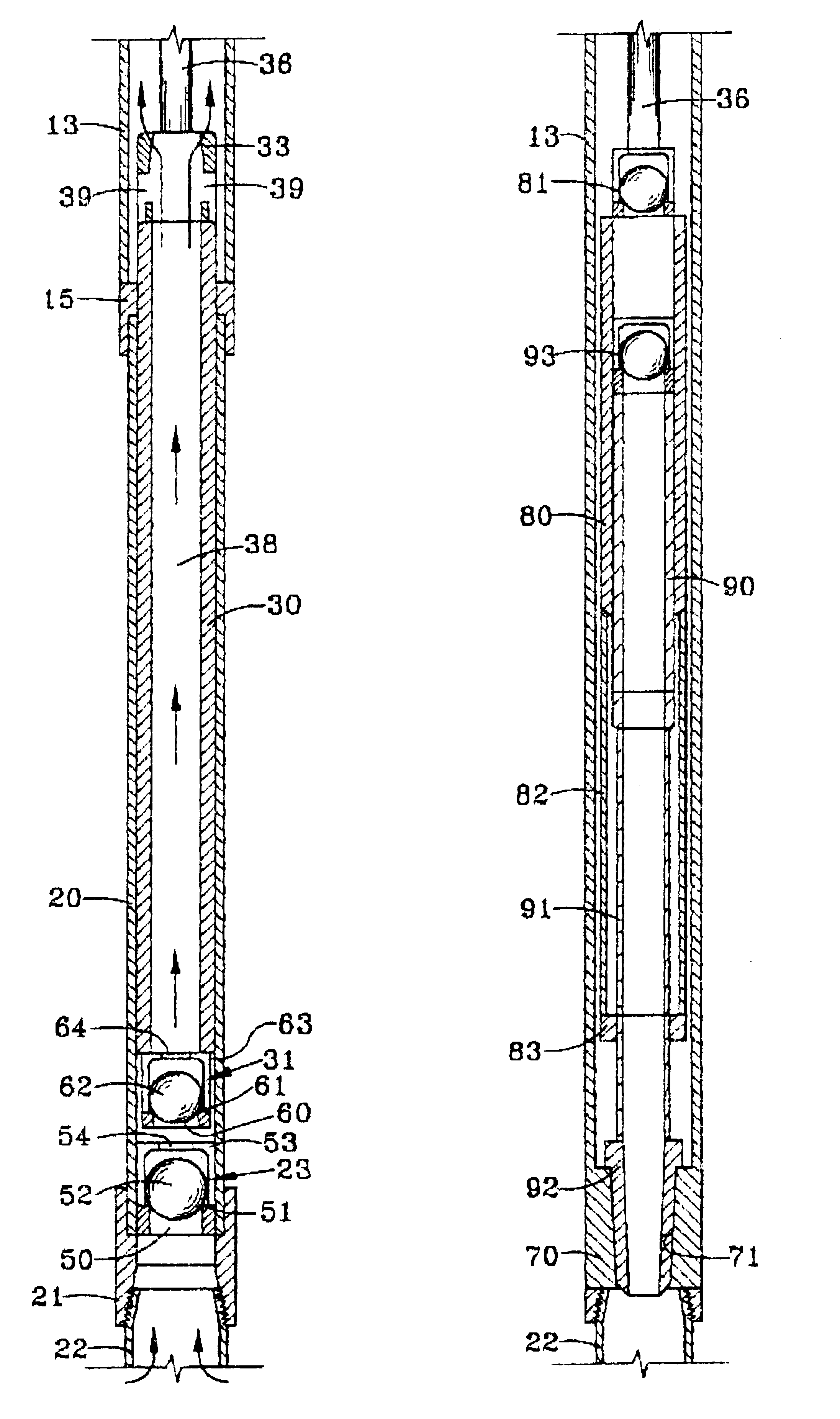
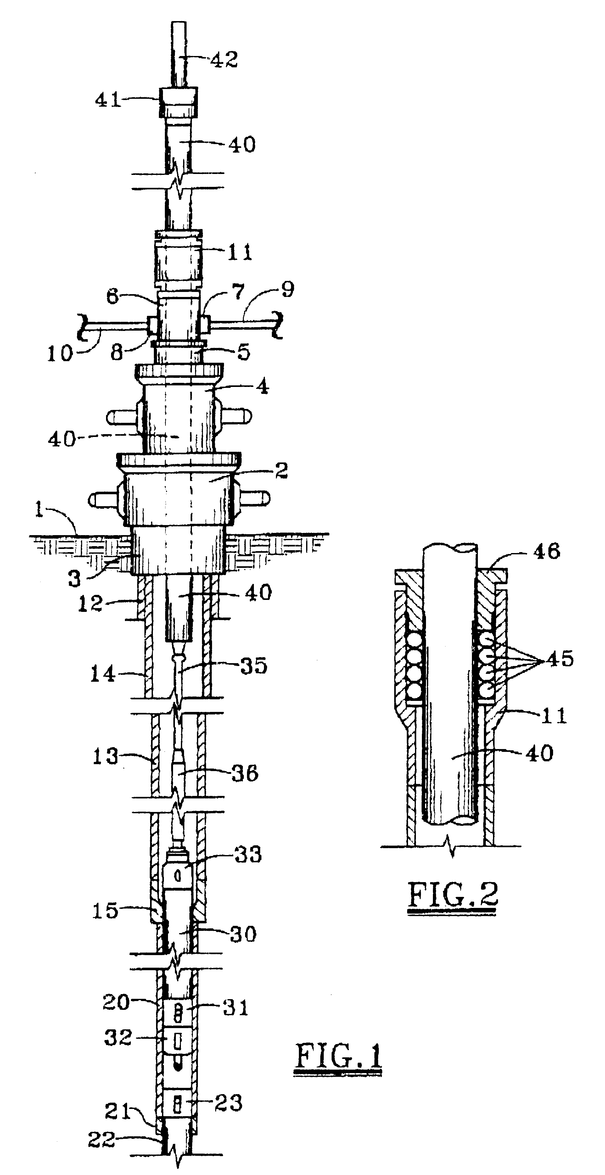
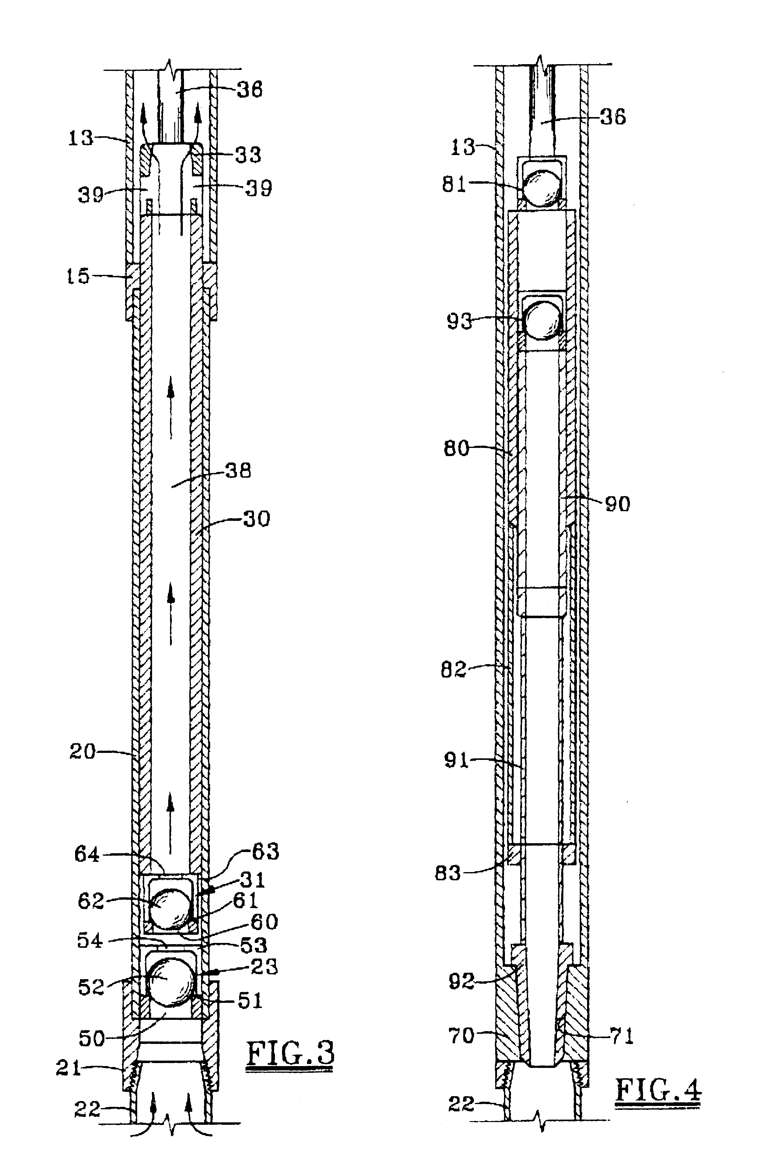
Referring first to FIG. 1, there is shown a well, for example, an oil well for producing hydrocarbon fluids from a hydrocarbon bearing formation substantially below the surface of the earth. The surface is represented at 1. The well is provided at the surface 1 with a wellhead which includes a casing head 2 attached to the upper end of surface casing 3. Surmounted on the casing head 2 is a tubing head 4, a tubular spool 5 and a flow head 6. The flow head 6 may be provided with outlets 7 and 8. Outlet 7 is shown connected to a flow line 9. Outlet 8 may be connected to a bleeder line 10. Mounted on the top of the flow head 6 is a stuffing or packing box 11 for the polished rod 40 which is shown in more detail in FIG. 2 and will be more filly described hereafter with reference thereto.

As previously stated, the casing head 2 is supported on the upper end of the surface casing 3. The casing head 2 supports a production casing 12 and the tubing head 4 supports a tubing or production strin...


PUM


Abstract

A fluid pumping apparatus for pumping fluids from a well, through a production string comprising: a tubular pump plunger concentrically disposed in a sliding and sealing fit with a tubular pump barrel. A cylindrical polished rod, the lower end of which is connected to a string of rods, extends upwardly through a sealing assembly for sliding and sealing reciprocation. The diameter of the polished rod being at least as great as the outside diameter of the pump plunger. A power device is operatively connected to the polished rod for lifting and lowering the polished rod, the string of rods and either the barrel or plunger; such that no fluid is remove from the production string on the upward movement of the polished rod.

Description

1. Field of the InventionThe present invention pertains to pumping apparatus. More specifically, the present invention pertains to reciprocating pumps of the type used for producing fluids from subsurface wells.2. Description of the Prior ArtSubsurface wells, particularly those for producing underground hydrocarbon fluids, typically include a string of tubing or "production string" which extends from near the bottom of the well to the surface for flow of fluids through a flow line connected to the production string at the surface. For wells which do not have enough pressure to produce fluids on their own, some type of pumping system must be employed.Pumps for lifting subsurface fluids to the surface of an oil well have been in existence for many years. One type of pump, typically referred to as a lift pump, usually includes a tubular barrel (which may be a portion of the production tubing) and a cooperating plunger assembly which reciprocates therein. The plunger assembly may be att...

Claims


Application Information

Patent Timeline
Patent Type & Authority Patents(United States)
IPC IPC(8): F04B47/02F04B47/00F04B11/00
CPCF04B11/00F04B47/02
Inventor SKILLMAN, MILTON
Owner SKILLMAN MILTON
Why Eureka
Try Eureka