Building Management and Appliance Control System

a building management and control system technology, applied in the field of energy management systems, can solve the problems of long time-consuming and laborious, increased energy demand, and inability to meet the needs of sub-stations idle, so as to avoid excess energy costs, avoid over-burdening local power utilities, and inefficient energy use

Inactive Publication Date: 2015-03-05
PEAKNRG
View PDF3 Cites 36 Cited by
  • Summary
  • Abstract
  • Description
  • Claims
  • Application Information

AI Technical Summary

Benefits of technology

[0013]In areas where the power grid suffers from blackouts and brownouts, or is generally unreliable, the system of the present invention ensures adequate power is available to run the appliance through the use of the battery unit or running the battery unit in parallel with the power grid. In areas where the main source of power is alternative energy, such as solar or wind, power may not be available during night time or times of no wind, the system of the present invention ensures that power is available as well. To ensure the battery unit of the system can provide the needed power, the system of the present invention charges the battery at an optimum time based on the information received through the energy cloud to avoid excess energy cost, over burdening the local power utilities, and inefficient energy use among other factors. The system of the present invention allows for charging of the batteries when power is present and then allows the power to be used at a later time, regardless of the presence of utility provided power.
[0014]The system can charge the batteries by way of a trickle charge, a normal charge, or a fast charge, depending on various factors during the charging cycle such as available power, current power demand on utility providers, and cost of power. The system contemplates the use of lead-acid batteries, Lithium Ion batteries, and Nickel Metal Hydride batteries. However, the system can be used with other energy storage technologies, such as hydrogen fuel cells. Some utilities charge more for power used during peak times and less during off-peak times. The system of the present invention allows for the shifting of grid power usage to off-peak times when the cost of power is cheaper. If the batteries need to be charged during peak times, the system may use a trickle charge to help reduce energy costs. During off-peak times, or when power is available from a local source, such as solar or wind, the system may use a normal charge or a fast charge. Additionally, if the system has stored power remaining before the next cycle to charge the batteries, the system may return the power to grid so it can be used elsewhere. Further, during peak times and the battery unit is not being utilized by the user, the stored electricity can be returned to the power grid to relieve the burden on local utility providers producing energy. In some areas, the user will receive credit for the returned power, thereby reducing the user's utility costs.

Problems solved by technology

Fluctuating usage has long been an issue for electrical utility providers.
Increased energy demand (peaks) creates problems that can range from overloaded transformers, quickly spinning up generators that try meet demand, or potential blackout situations.
Low demand (valleys) also has its issues, creating the need for sub-stations that sit idle in anticipation of the next energy peak.
These complex programs have proven to not be as effective as hoped.
Potential “solutions” expect consumers to change their routine or suffer the consequences of higher energy pricing or increased temperatures in their homes, requiring them to pay attention and to make some very difficult decisions, ultimately sacrificing either price or comfort.
These devices offer complicated options to an already complicated issue and have yet to offer any significant long-term value.
Over the past decade, utilities have tried incentivizing consumers to conserve, with most programs generating weak results.
The most recent tactics has cost utilities significantly and the increasing program complexity causes utilities to question if the conservation efforts are really what are necessary to help stabilize the electrical grid.
In the past, batteries have had a difficult time gaining traction for various reasons.

Method used


Image

  • Building Management and Appliance Control System
  • Building Management and Appliance Control System
  • Building Management and Appliance Control System

Examples


Embodiment Construction

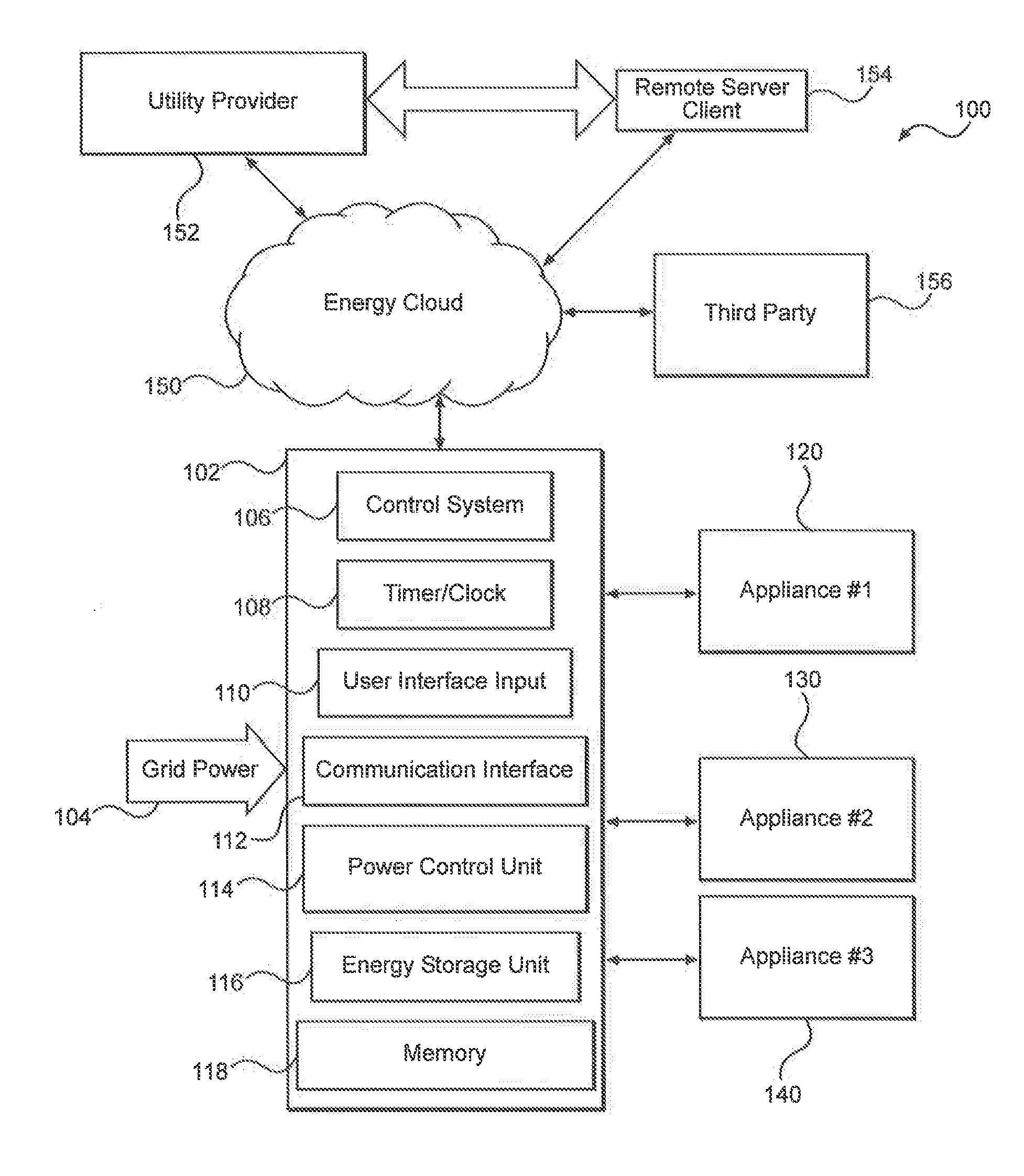
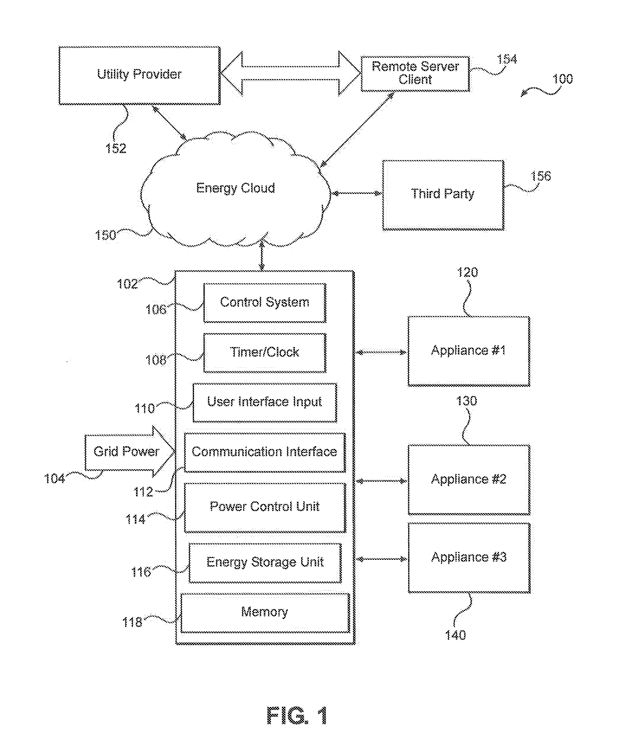
[0021]Referring initially to FIG. 1, a system-level block diagram of the present invention is shown and generally designated 100. System 100 includes an appliance control unit 102 that receives grid power 104. Grid power 104 can be supplied by traditional electric power utilities, solar panels, wind turbines, hydro-electric generators, geothermal power, and any other source of electrical power. The appliance control unit 102 is in communication with an energy cloud 150, which in turn is in communication with the utility provider 152, a remote server client 154, and a third party 156. The appliance control unit 102 is also in communication with appliances 120, 130, and 140, respectively.

[0022]Internally, appliance control unit 102 includes a control system 106, a timer / clock 108, a user interface 110, a communication interface 112, a power control unit 114, an energy storage unit 116, and memory 118. The control system 106 of the present invention may include a central processing uni...


PUM


Abstract

The building management and appliance control system of the present invention includes an appliance control unit capable of monitoring and regulating the energy use of connected appliances based on information gathered from an energy cloud. The energy cloud is a network of remote server clients hosted on the Internet used to store, manage, and process energy data which are in communication with utility providers and third party systems. The appliance control unit includes a control system which communicates between and controls the overall function of the modules within the unit such as the user interface input, communication interface, power control unit, and battery unit. The appliance control unit uses all of the information available from the energy cloud to determine the optimum time to operate the attached appliances and when and how fast to charge the battery unit to ensure adequate power for the appliances at all times.

Description

RELATED APPLICATION[0001]The present application claims the benefit of priority to U.S. Provisional Application Ser. No. 61 / 859,167, filed on Jul. 26, 2013, entitled “Building Management and Appliance Control System,” and currently co-pending.FIELD OF INVENTION[0002]The present invention relates generally to energy management systems. This present invention relates more particularly, but not exclusively, to a building management and appliance control system configured to provide consistent power at all times independent of the dynamic fluctuations in available power from the power grid.BACKGROUND OF THE INVENTION[0003]The world's traditional electrical network—simple and linear, with centralized energy production—is undergoing a transformation to a much more complex, interconnected, and interactive model: the Smart Grid. However, for this network to become intelligent, users will require connectivity, simplicity, and security, all without compromising end user lifestyle.[0004]Fluctu...

Claims


Application Information

Patent Timeline
Patent Type & Authority Applications(United States)
IPC IPC(8): G05F1/66H04L29/06H04L12/28
CPCG05F1/66H04L67/42H04L12/2803H04L67/02H04L67/10Y04S20/12H02J3/32H02J2310/64H02J2310/14H02J2310/10H02J2300/28H02J2300/26H02J2300/20H02J3/381H02J13/00004H02J13/00034H02J3/14Y02A30/60Y02B10/10Y02B70/30Y02B90/20Y02E10/76Y04S20/222Y04S50/10Y04S20/20Y02B70/3225H02J13/00002Y02E70/30Y04S10/123Y04S20/242H02J2310/54H02J3/00H02J3/38Y02E10/56Y02E40/70H02J13/00H02J7/0068
Inventor CLIFTON, ERIC DOUGLAS
Owner PEAKNRG
Why Eureka
Try Eureka