Control apparatus for hybrid driving apparatus

a control apparatus and hybrid technology, applied in the direction of process and machine control, instruments, etc., can solve the problems of easy actualization of torque variation, hard to exclude, and torque variation in the torque of the output member, so as to facilitate interlocking operation, correct or compensate the dimensional tolerance and dimensional accuracy of each of the engagement elements. , the effect of large engagement for

Inactive Publication Date: 2010-10-28
TOYOTA JIDOSHA KK
View PDF7 Cites 22 Cited by
  • Summary
  • Abstract
  • Description
  • Claims
  • Application Information

AI Technical Summary

Benefits of technology

[0040]According to this aspect, the engaging device is constructed as an interlock engaging apparatus in which the engagement elements are engaged by that some physical engagement parts (e.g. projections such as dog teeth, or various concavo-convex parts, or the like) formed in each of the engagement elements, such as a dog clutch, interlock with each other. This type of interlock engaging apparatus is an engaging device of a so-called rotational synchronization engaging type in which the aforementioned rotational synchronization between the engagement elements is essential in the engagement, as opposed to an engaging apparatus of a friction engagement type in which the engagement elements are engaged by various friction forces acting on the engagement elements. Although the control can be complicated in that it may further need phase control among the rotational elements according to circumstances, the interlock engaging apparatus easily obtains a larger engagement force than that in the friction engaging apparatus, and it is preferable as the reaction element in the fixed speed-change mode.
[0041]On the other hand, in this type of interlock engaging apparatus, in many cases, there is a gap between the engagement parts which are adjacent to each other in a rotation direction even in the state that interlock parts formed in each of the engagement elements interlock with each other, for example, in order to facilitate an interlock operation, or in order to correct or compensate the dimensional tolerance and dimensional accuracy of each of the engagement elements. Therefore, in the process that the output torque of the first electric motor is reduced and that the reaction torque is transferred to the engaging device, physical impact referred to as so-called “chatter or rattle” easily occurs. This type of physical impact basically causes the deterioration of drivability of the vehicle to a greater or lesser extent.
[0042]According to this aspect, the degree of the reduction in the output torque of the first electric motor is made relatively small at the beginning of the reduction period (which is equivalent to the aforementioned change period). Thus, the degree of the physical impact described above is reduced, thereby to limit or control the adverse effect on the drivability. Moreover, with regard to the at least one portion of the reduction period excluding the beginning, i.e. the remaining period excluding the beginning as a preferred form, the degree of the reduction is relatively increased, and the inefficient use of an energy resource caused by the lengthened reduction period is limited or controlled. In other words, according to this aspect, there is provided such a practically high benefit that the speed-change mode can be changed from the stepless speed-change mode to the fixed speed-change mode as quickly as possible while facilitating the transfer of the reaction torque to the engaging device as much as possible.

Problems solved by technology

In the conventional technology, however, there is no description about the prevention of the torque variation during the speed-change period, and the torque variation is easily actualized as the deterioration of drivability or the like.
On the other hand, even if it is tried to apply the technology disclosed in the patent document 2 to the aforementioned problem, generally, a brake hydraulic pressure does not always accurately indicate the torque capacity of the brake no matter how fit they are set in advance, and if the control of the torque capacity of the friction engagement apparatus of this type exists in the limit of the torque variation of the output member, it would be hard to exclude such a possibility that the torque variation occurs in the torque of the output member to the extent that it can be actualized as the deterioration of drivability.
In other words, the conventional technology has such a technical problem that the torque variation of the output member is hardly limited or controlled at the time of transition from a stepless speed-change state mode to a fixed speed-change state mode.

Method used


Image

  • Control apparatus for hybrid driving apparatus
  • Control apparatus for hybrid driving apparatus
  • Control apparatus for hybrid driving apparatus

Examples


first embodiment

Structure of Embodiment

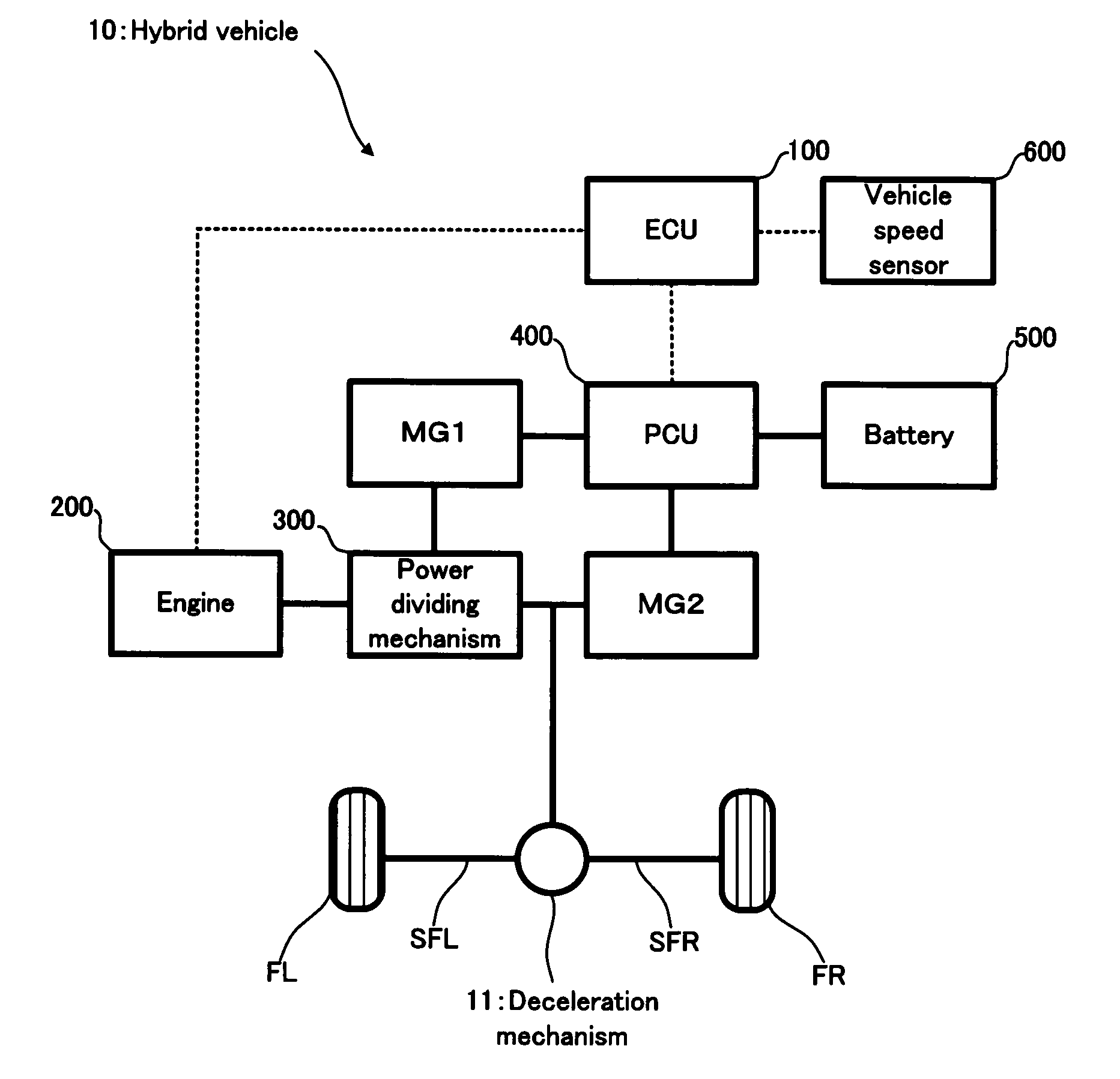
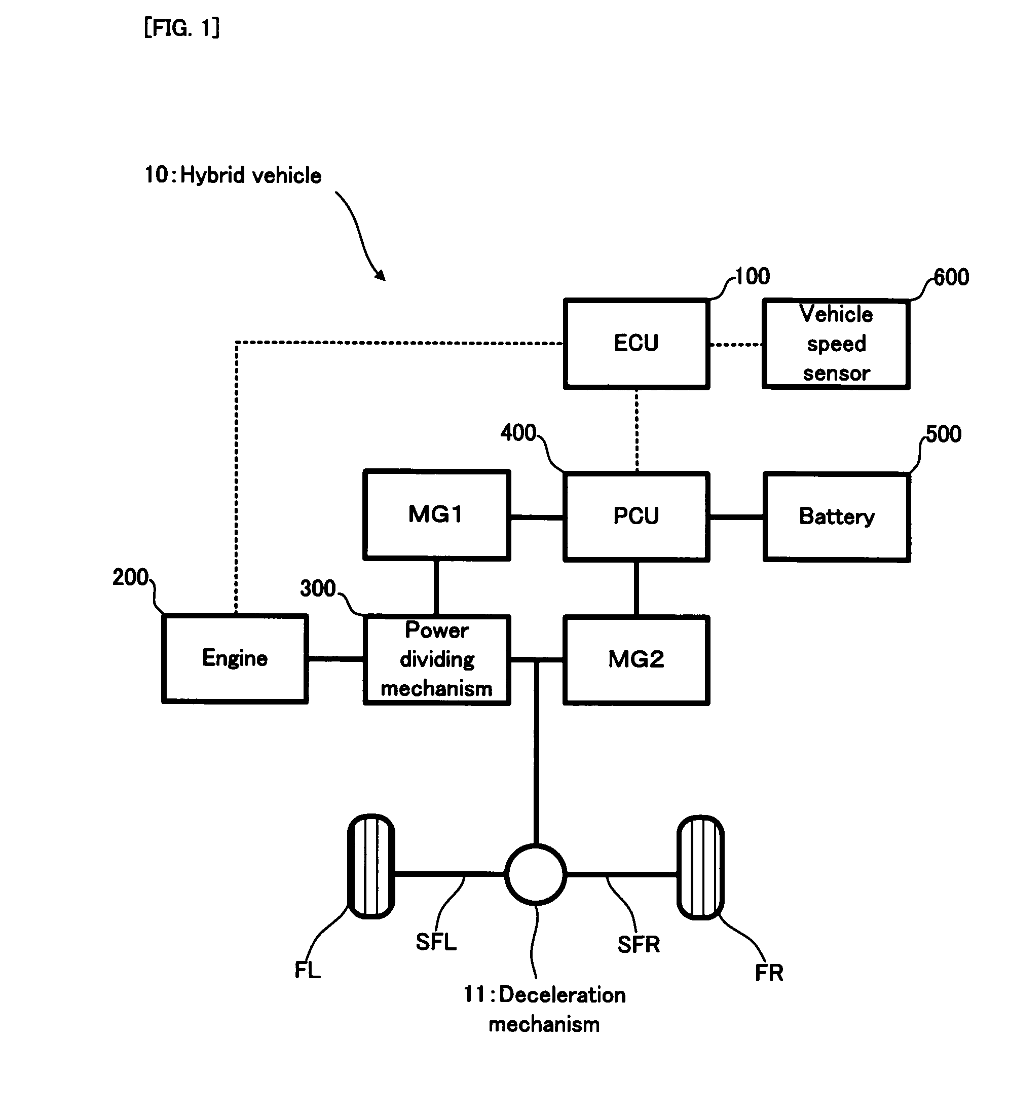
[0081]Firstly, with reference to FIG. 1, an explanation will be given on the structure of a hybrid vehicle 10 in a first embodiment of the present invention. FIG. 1 is a schematic configuration diagram conceptually showing the structure of the hybrid vehicle 10.

[0082]In FIG. 1, the hybrid vehicle 10 is provided with an ECU 100; an engine 200; a power dividing mechanism 300; a motor generator MG1 (hereinafter abbreviated to a “MG1”, as occasion demands); a motor generator MG2 (hereinafter abbreviated to a “MG2”, as occasion demands); a PCU (Power Control Unit) 400; a battery 500; and a vehicle speed sensor 600. The hybrid vehicle 10 is one example of the “vehicle” of the present invention.

[0083]The ECU 100 is provided with a CPU (Central Processing unit), a ROM (Read Only Memory), a RAM, and the like. The ECU 100 is an electronic control unit, adapted to control the entire operation of the hybrid vehicle 10, and it is one example of the “control apparatus for...

embodiment

Operation of Embodiment

Details of Speed-Change Mode

[0113]The power dividing mechanism 300 functions as the speed-changing apparatus or gearbox of the hybrid vehicle 10. At this time, in the power dividing mechanism 300, the following two types of speed-change modes are realized: a stepless speed-change mode and a fixed speed-change mode.

[0114]When the power dividing mechanism 300 drives the engine 200 in the condition that the corresponding rotational element (which is the sun gear 341 of the second planetary gear mechanism 340 in this case) is not fixed by the clutch mechanism 350, the engine torque is divided into and transmitted to the motor generator MG1 and the drive shaft 320, by the power dividing mechanism 300. This is due to the differential operation of the power dividing mechanism 300. By increasing or decreasing the rotational speed of the motor generator MG1, the combustion rotational speed NE of the engine 200 is controlled in a stepless (or continuous) manner. This ...


PUM


Abstract

A speed-change mode is changed from a stepless speed-change mode to a fixed speed-change mode while limiting or controlling the torque variation of an output member.
An ECU 100 performs speed-change control. In the speed-change control, if a request is provided to change the speed-change mode from the stepless speed-change mode to the fixed speed-change mode, the ECU 100 engages the clutch mechanism 350 after the rotational synchronization and the phase synchronization of the clutch mechanism 350. After engaging the clutch mechanism 350, the ECU 100 gradually reduces the output torque of a motor generator MG1 and gradually changes a reaction element from a sun gear 331 to a sun gear 341. At this time, the output torque of a motor generator MG2 is also gradually reduced. The output torque of the motor generator MG2 is corrected to limit or control a change in the output torque of a drive shaft 320, on the basis of the gear ratio between the rotational elements of a power dividing mechanism 300 and the reduction amount of the output torque of the motor generator MG1.

Description

TECHNICAL FIELD[0001]The present invention relates to a control apparatus for a hybrid driving apparatus, which is equipped with an internal combustion engine and an electric motor as the power source of a vehicle.BACKGROUND ART[0002]As this type of driving apparatus for a hybrid vehicle, the following apparatus has been suggested: a driving apparatus provided with such a brake that a power source, an output member, and a first motor generator are connected to a power transfer mechanism, which is provided with a plurality of pairs of differential mechanisms, and that the rotation of any of the rotational elements of the power transfer mechanism is selectively stopped, to thereby fix a ratio of the number of rotations between the power source and the output member in an overdrive state (e.g. refer to a patent document 1). According to the driving apparatus for the hybrid vehicle disclosed in the patent document 1 (hereinafter referred to as a “conventional technology”), the hybrid dr...

Claims


Application Information

Patent Timeline
Patent Type & Authority Applications(United States)
IPC IPC(8): B60W10/10B60W20/00G06F19/00B60K6/365B60K6/445B60K6/54B60L50/16B60W10/08
CPCB60K1/02Y10T477/26B60K6/445B60K6/547B60L11/14B60L2240/421B60L2240/423B60L2240/441B60W10/06B60W10/08B60W10/115B60W20/00B60W30/19B60W2510/0638B60W2510/0685B60W2510/081B60W2520/10B60W2710/0666B60W2710/083F16H3/727F16H61/0437F16H2037/0873F16H2061/6603Y02T10/6239Y02T10/6286Y02T10/642Y02T10/7077Y02T10/70B60K6/365B60L50/16Y02T10/62Y02T10/64Y02T10/7072B60W10/02B60W20/40
Inventor EBUCHI, HIROAKIKIMURA, HIROMICHIMITSUYASU, MASAKI
Owner TOYOTA JIDOSHA KK
Why Eureka
Try Eureka