Power transmission apparatus

a technology of power transmission apparatus and clutch, which is applied in the direction of mechanical actuators, mechanical apparatus, transportation and packaging, etc., can solve the problems of reducing responsiveness, structural expansion of clutch pack, and such drawbacks of power transmission apparatus, so as to reduce drag torque, high responsiveness, and no high precision machining

Active Publication Date: 2015-02-05
TOYOTA JIDOSHA KK
View PDF4 Cites 5 Cited by
  • Summary
  • Abstract
  • Description
  • Claims
  • Application Information

AI Technical Summary

Benefits of technology

[0031]The present invention can provide a power transmission apparatus provided with the clutch device which can require no high precision machining and reduce the drag torque, as well as can have the high responsiveness and the large engagement force.

Problems solved by technology

The power transmission apparatus thus required encounters such a problem that the clutch pack is structurally enlarged.
In addition, the enlarged gaps between the friction engagement elements of the clutch pack leads to the strokes of the friction engagement elements of the clutch pack to be brought into engagement with one another, so that the power transmission apparatus encounters such a problem that the responsiveness is lowered.
However, the power transmission apparatus has such a drawback to generate the drag torque between the friction engagement elements of the clutch pack prior to an engagement state of the clutch device with the magnetic force of the electromagnet coil.
The above clutch device is required to reduce the rotational speed of the actuator with a high reduction gear to obtain a predetermined frictional engagement force of the clutch device, so that the power transmission apparatus encounters such a problem that the responsiveness of the clutch device is further lowered in addition to the increased gaps between the friction engagement elements of the clutch device.

Method used


Image

  • Power transmission apparatus
  • Power transmission apparatus
  • Power transmission apparatus

Examples


first embodiment

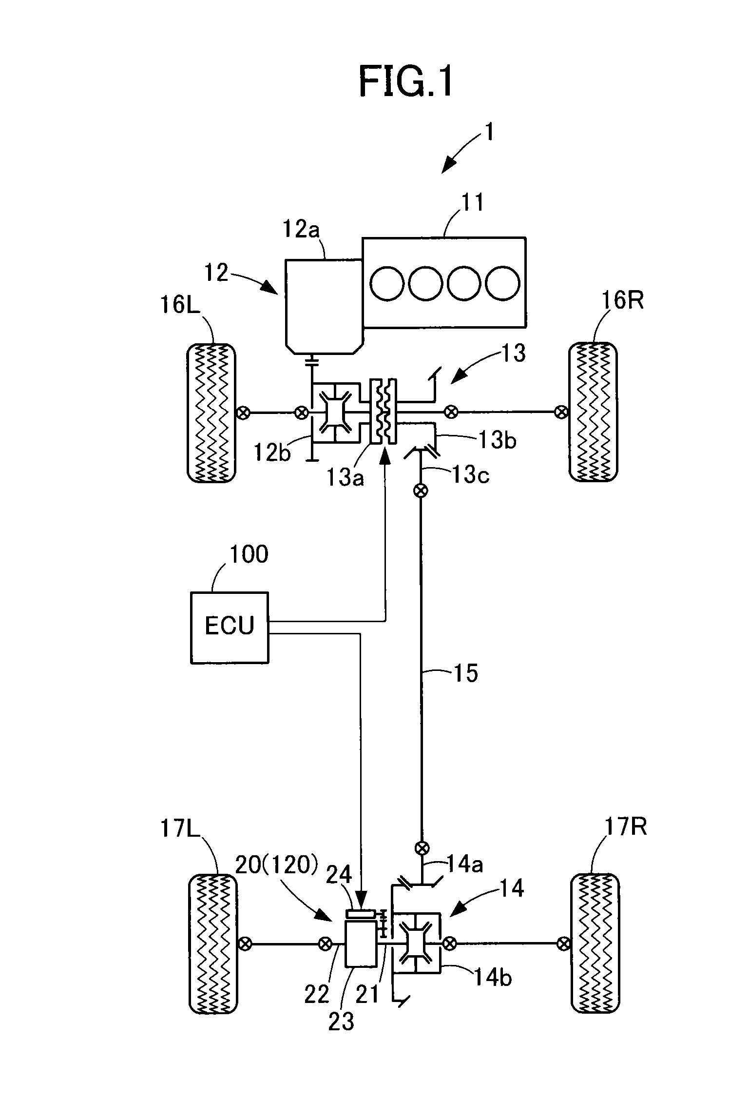
[0047]As shown in FIG. 1, the vehicle 1 bases a front engine front drive type, and is thus constituted by what is called a part time four-wheel drive vehicle (hereinafter simply referred to as a “part time 4WD”) which is adapted to automatically be changed to selectively take a front two wheel drive state or a four-wheel drive state.

[0048]The vehicle 1 comprises an engine 11, a transaxle 12, a transfer 13, a rear differential 14, a propeller shaft 15, left and right front wheels 16L, 16R, left and right rear wheels 17L, 17R, and a power transmission apparatus 20. The vehicle 1 is further provided with an electronic control unit (hereinafter simply referred to as an “ECU”) 100 for controlling various devices and mechanisms mounted on the vehicle 1.

[0049]The engine 11 is constructed by a horizontally placed straight four-cylinder engine which may be replaced by any other types of engine. For example, the engine 11 may be constructed to have a single cylinder or multi-cylinders such as...

second embodiment

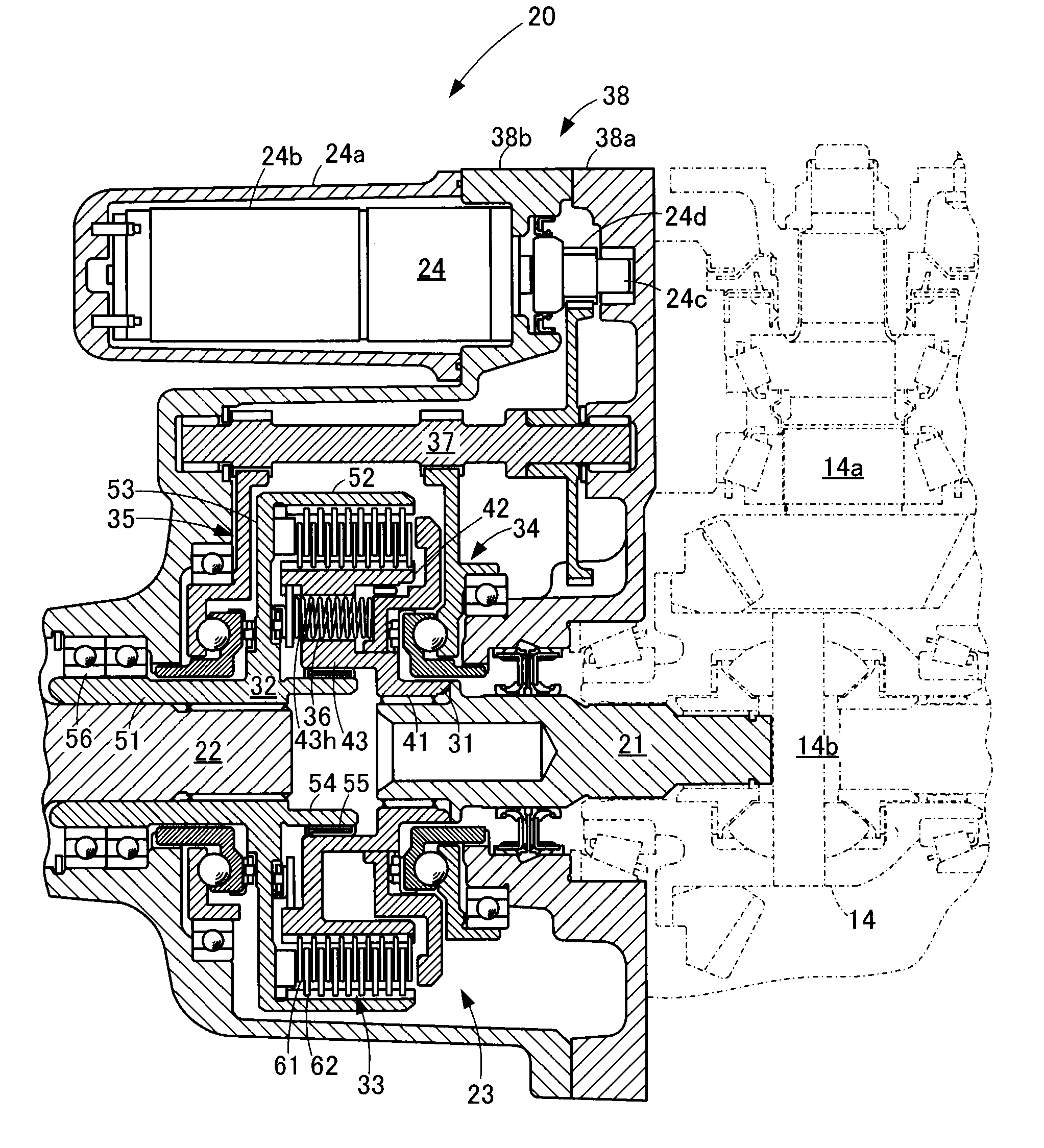
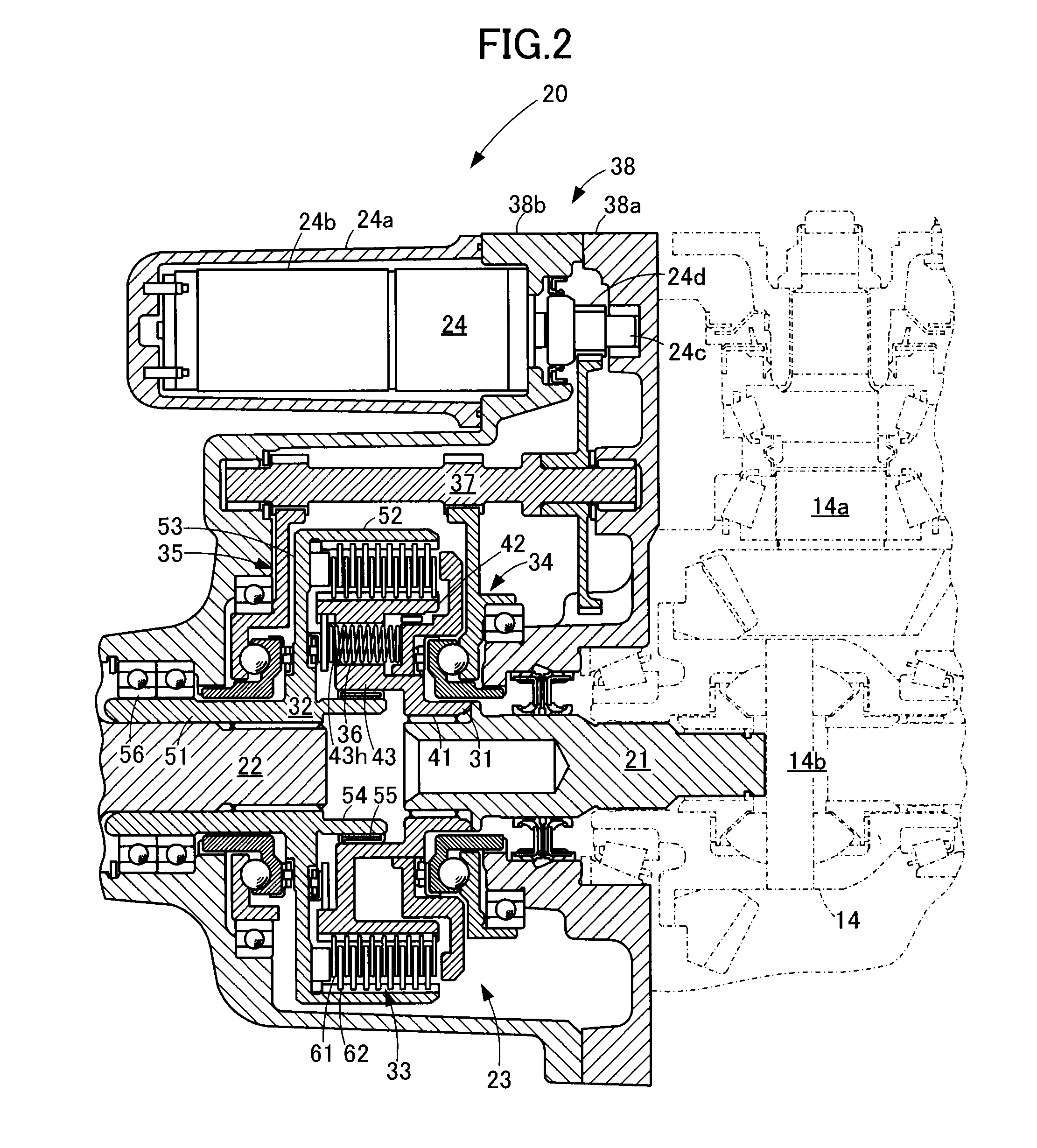
[0114]A power transmission apparatus 120 according to the second embodiment to be applied to the vehicle 1 is constructed to have a clutch device 123 in lieu of the clutch device 23 according to the first embodiment, and other elements and parts the same in construction as those of the power transmission apparatus 120 according to the first embodiment. Therefore, the other elements and parts the same in construction as those of the power transmission apparatus 120 according to the first embodiment will be described hereinafter with the same reference numerals and legends used for explanation in the first embodiment shown in FIGS. 1 to 4. Only the elements and parts different in construction from those of the power transmission apparatus 120 according to the first embodiment will be described hereinafter.

[0115]The power transmission apparatus 120 comprises an input shaft 21, an output shaft 22, the clutch device 123, and an actuator 24.

[0116]The clutch device 123 is constructed with ...


PUM


Abstract

A power transmission apparatus comprises an input shaft, an output shaft, a clutch device, and an actuator. The clutch device comprises a clutch hub, a clutch housing, a clutch pack, an input side cam mechanism for pressing the clutch pack toward the output shaft, an output side cam mechanism for pressing the clutch pack toward the input shaft, a return spring for urging the clutch pack to have its elements moved away from each other, and a drive shaft having an input side gear for transmitting the driving force of the actuator to the input side cam mechanism, and an output side gear for transmitting the driving force of the actuator to the output side cam mechanism.

Description

TECHNICAL FIELD[0001]The present invention relates to a power transmission apparatus, and more particularly to a power transmission apparatus having a clutch device operative with an output torque of an actuator.BACKGROUND ART[0002]In general, a clutch device of this kind forming part of a power transmission apparatus is provided with a cam mechanism that can increase an output torque of an actuator to enhance a frictional engagement force of the clutch device, thereby increasing a torque transmission amount of a power transmission apparatus. The torque increasing function of the cam mechanism as such makes it possible not only to downsize the actuator but also to realize designing a small clutch pack.[0003]The cam mechanism is schematically shown in FIG. 11 to comprise a drive side cam plate 101 driven by the actuator to rotate in a direction shown by an arrow “a”, a driven side cam plate 102, and a spherical member 103. The spherical member 103 is sandwiched between a cam surface ...

Claims


Application Information

Patent Timeline
Patent Type & Authority Applications(United States)
IPC IPC(8): F16D13/52B60W10/11B60W10/02
CPCF16D13/52B60W10/11B60W10/02B60K17/3515B60K23/0808F16D23/12F16D28/00F16D2023/123
Inventor YOSHIMURA, TAKAHIRO
Owner TOYOTA JIDOSHA KK
Why Eureka
Try Eureka