

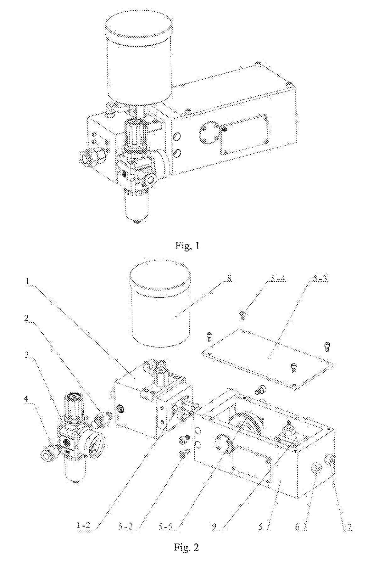
Continuous supply precision minimum quantity lubrication pump supporting different lubrication conditions
a lubricant supply pump and precision technology, applied in the direction of lubricating pumps, mechanical equipment, engine pressure, etc., can solve the problems of high production cost, extreme damage to the environment, and low utilization rate, so as to improve the cooling and lubricating effect of the machining area and the surface quality of the workpiece machining, the danger caused by the failure of the pneumatic system of the machine tool is greatly reduced, and the liquid supply precision is low
- Summary
- Abstract
- Description
- Claims
- Application Information
AI Technical Summary
Benefits of technology
Problems solved by technology
Method used
Image

Examples
Embodiment Construction
[0045]The present invention will be further described below in conjunction with the g drawings and specific embodiments.
[0046]It should be noted that the following detailed description is illustrative and intended to provide a further description of the present application. All technical and scientific terms used herein have the same meanings as commonly understood by those of ordinary skill in the art to which the present invention belongs, unless otherwise indicated.
[0047]It should be noted that the terms used herein are merely for the purpose of describing particular embodiments, and are not intended to limit the exemplary embodiments of the present application. As used herein, the singular forms are also intended to include the plural forms, unless the context clearly indicates otherwise, and it is also understood that when the terms “include” and / or “comprise” are used in the specification, they indicate the presence of features, steps, operations, devices, components, and / or c...
PUM
 Abstract
Description
Claims
Application Information