
Standby loss prevention module, transformer system including same, and methods relating thereto

a technology of transformer system and standby, which is applied in the direction of signaling system, process and machine control, instruments, etc., can solve the problems of increasing the energy cost of electrical power, affecting the operation increasing the cost of electrical power generation, so as to reduce the power requirement

Inactive Publication Date: 2008-07-01
MARENCO TECH GROUP
View PDF4 Cites 37 Cited by
  • Summary
  • Abstract
  • Description
  • Claims
  • Application Information

AI Technical Summary

Benefits of technology

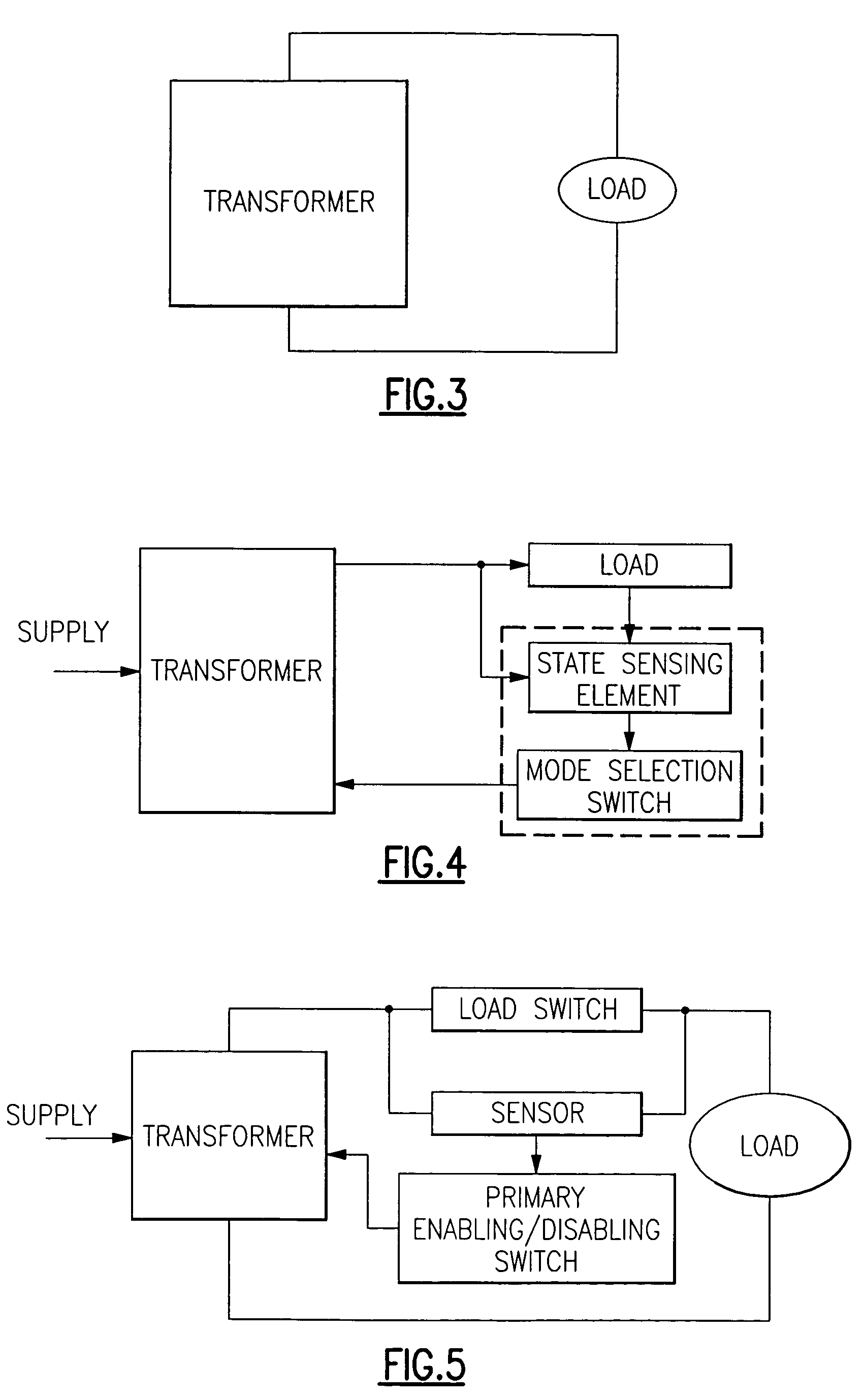
"The present invention provides a standby loss prevention module for transformers that reduces power requirements and associated costs. The module includes a sensor and control switch that detect the mode of load operation and activate or deactivate the transformer accordingly. The module can be connected to any conventional transformer and can be wireless. The invention also includes an improved transformer with the standby loss prevention module that includes a sensor, control switch, and other components to detect and communicate the mode of load operation. The standby loss prevention module can be printed on a circuit board and can be used in single or multi-phase transformers. The invention provides a solution for reducing standby loss in transformers and improving their efficiency."

Problems solved by technology

Recent events in different geographical regions of the United States have witnessed both sky-rocketing electrical power energy cost increases and massive black-outs due to the age of the grid and over demand by consumers for electrical power.
Undesirable and disruptive brown-outs and rolling black-outs have also become more common and necessary in recent times due the ever increasing demands for electrical power.
The increased demand for electrical power simply cannot be met by building new power plants because the lag time associated with bringing new power plants on-line or up-grading existing power plants is relatively long compared to the fluctuating but steadily increasing demands for electrical power.
The problem with these transformers is that they are wired in the ON state at all times. They thus draw electricity 24 hours a day even though the devices are only needed a few hours each day.
A great amount of energy is wasted during those idle hours.

Method used


Image

  • Standby loss prevention module, transformer system including same, and methods relating thereto
  • Standby loss prevention module, transformer system including same, and methods relating thereto
  • Standby loss prevention module, transformer system including same, and methods relating thereto

Examples


Embodiment Construction

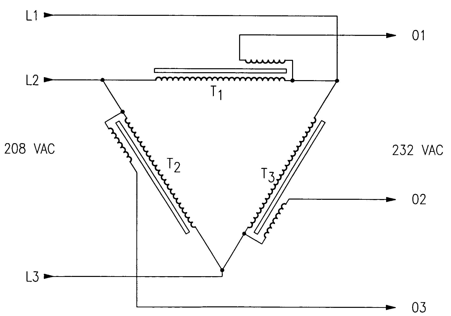
[0071]The following description is provided in conjunction with the accompanying drawing figures which are to be fully considered as a part of this disclosure. The invention herein is being elaborated mainly referring to the booster type of transformers. A person skilled in the art, however, will appreciate that the various aspects of the invention can be readily applied to other types of transformers and a similarly elaborated description is possible for these embodiments.

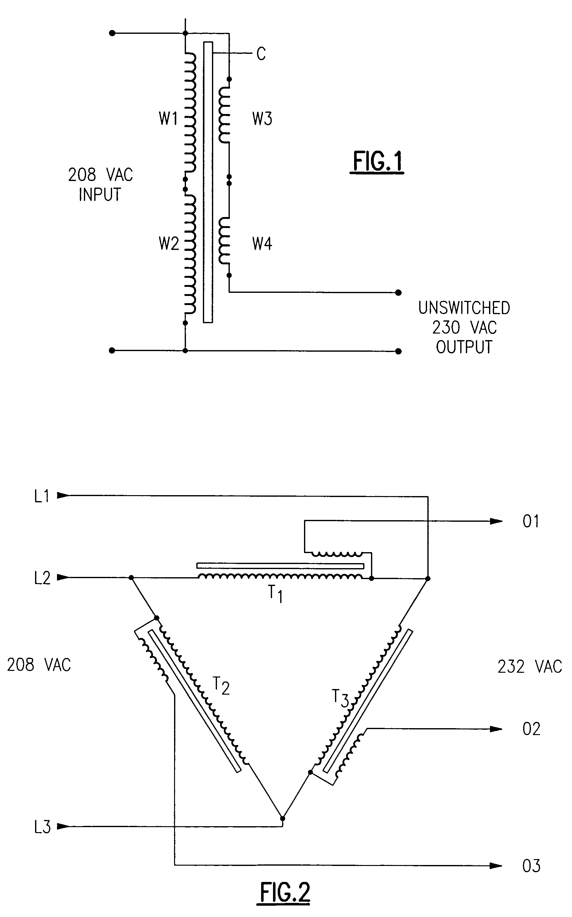
[0072]With reference now to FIG. 1, there is shown a conventional single-phase booster type transformer having four windings or coils W1, W2, W3, W4 and a core C. The windings W1 and W2 are high voltage input (primary) windings and are connected in series across the mains. The windings W3 and W4 are low voltage (secondary) windings and are connected in series with each other and the output nodes as shown in FIG. 1. This circuit exploits Lenz's law of induction for its operation. According thereto, a voltage across...


PUM


Abstract

Methods and apparatus for controlling power to a load device. The apparatus include a standby loss prevention module or a transformer system including the module. The module and system are directed to sensing load requirements and controlling a transformer accordingly to reduce power consumption when the load is in a stand by mode. One method includes interposing a control switch between an electrical supply and a load device, determining when the load device requires full-level operational power, activating the control switch to interpose a step-up transformer between the electrical supply and the load device, providing full-level operational power to the load device, and deactivating the step-up transformer when the load device is not in use.

Description

CROSS REFERENCE TO RELATED APPLICATIONS[0001]The present application claims the benefit of priority from U.S. Provisional Application Ser. No. 60 / 537,107 filed Jan. 17, 2004 and U.S. Provisional Application Ser. No. 60 / 583,282 filed Jun. 25, 2004 both of which are incorporated herein by reference in their entirety.BACKGROUND OF THE INVENTION[0002]1. Field of the Invention[0003]This invention relates in general to electronic control devices and, in particular, to electronic control devices for regulating supply power to electrical apparatus. More specifically, but without restriction to the particular embodiments hereinafter described in accordance with the best mode of practice, this invention relates to a standby loss prevention module and transformer system that may be employed in conjunction with a wide variety of electrical apparatus including industrial motors, large-volume air compressors, tanning equipment used in tanning salons, and other electrical apparatus requiring a tra...

Claims


Application Information

Patent Timeline
Patent Type & Authority Patents(United States)
IPC IPC(8): G08B23/00G05F1/12G05F1/14
CPCG05F1/14
Inventor NGUYEN, HAPNGUYEN, CHILINH
Owner MARENCO TECH GROUP
Learn More