Female crimp terminal

a technology of crimp terminals and crimps, which is applied in the direction of coupling device details, coupling device connections, coupling contact members, etc., can solve the problems of conspicuous defects, inability to insert the female crimp terminal into the housing, and greater resistance to insertion, so as to prevent bending force, enable compactification of the female crimp terminal, and secure the strength of the neck

Inactive Publication Date: 2003-02-25
JST MFG CO LTD
View PDF12 Cites 24 Cited by
  • Summary
  • Abstract
  • Description
  • Claims
  • Application Information

AI Technical Summary

Benefits of technology

is to prevent the bending force applied to the barrel from being transmitted to the upper parts of the rear ends of the side walls by making a notch in each side wall from the rear end of the body so as to divide the side wall into an upper part and a lower part, to secure strength of the neck and secure the function of the leaf spring, to prevent bending of the upper parts of the side walls and expansion of the upper wall, in turn, to ensure smooth insertion of the female crimp terminal into a cell of the housing, and to enable compactification of the female crimp terminal by shortening the longitudinal length of the neck.
In this female crimp terminal, if an electric wire, of which insulation is removed to expose the core, is placed in the cavity of the barrel and the retainers of the barrel are bent inward, the electric wire will be crimped in the barrel. If the female crimp terminal is inserted into the housing, and a male terminal is inserted into the body of the female crimp terminal, the male terminal will be inserted between the inside wall of the body and the leaf spring and connection between both terminals will be made. In that case, the bending force, which is generated when the retainers of the barrel are bent inward during crimping, will be transmitted via the neck to the rear end of the body. However, as each side wall is divided into an upper part and a lower part by the notch at the rear end thereof, the above-mentioned bending force will not affect the upper part of each side wall at the rear end of the body. Thus bending of the upper parts of side walls and expansion of the upper wall at the rear end of the body will be prevented. Accordingly, the insertion resistance when the female crimp terminal is inserted into the cell of the housing will not increase, and the female crimp terminal can be inserted smoothly into the cell of the housing. As the notches are not made in the neck itself or the notches are not made vertically between the neck and the body, the strength of the neck is secured. The above-mentioned bending force will be transmitted to the lower parts of the side walls at the rear end of the body. However, the insertion resistance when the female crimp terminal is inserted into the cell of the housing does not increase since the lower parts of the side walls at the rear end of the body are integrally formed on the bottom wall and have a higher rigidity than the upper parts, and even if the lower parts are deformed, they will be concaved inwardly. As the leaf spring is integrally formed on the front part of the body, the decrease in the rigidity resulting from making the notches does not affect the function of the leaf spring. Since the bending of the upper parts of the side walls and expansion of the upper wall at the rear end of the body are prevented as explained above, the female crimp terminal can be compactified by shortening the longitudinal length of the neck. As the upper wall is not worked, a retainer may be fitted on the upper side of the neck.
In the female crimp terminal according to the present invention a notch is made in each side wall at the rear end of the body to divide the side wall into an upper and a lower part so as to prevent the force for bending the barrel from being transmitted to the upper part of the side wall at the rear end, to prevent bending of the upper part of the side wall and expansion of the upper wall while securing the strength of the neck and securing the function of the leaf spring, and in turn, to eliminate any increase in insertion resistance when the female crimp terminal is inserted into a cell of the housing and ensure smooth insertion of the female crimp terminal into the cell of the housing. In turn, the female crimp terminal can be compactified by shortening the longitudinal length of the neck. As the upper wall is not worked, a retainer can be fitted onto the upper side of the neck.

Problems solved by technology

Should this happen, when the female crimp terminal is to be inserted into a cell of the housing, the resistance to the insertion may be greater or it may be impossible to insert the female crimp terminal into the housing.
In particular, when the female crimp terminal is compactified by shortening the longitudinal length of the neck, this defect will be conspicuous.
However, the insertion resistance when the female crimp terminal is inserted into the cell of the housing does not increase since the lower parts of the side walls at the rear end of the body are integrally formed on the bottom wall and have a higher rigidity than the upper parts, and even if the lower parts are deformed, they will be concaved inwardly.

Method used


Image

  • Female crimp terminal
  • Female crimp terminal
  • Female crimp terminal

Examples


Embodiment Construction

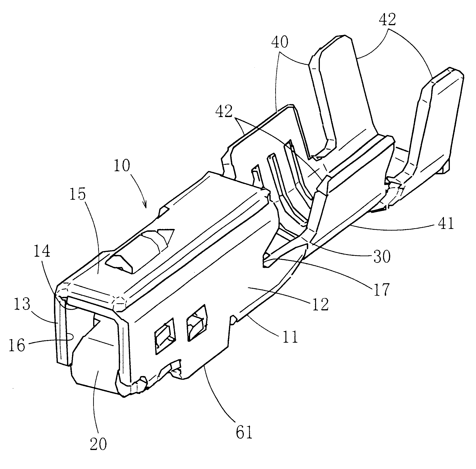
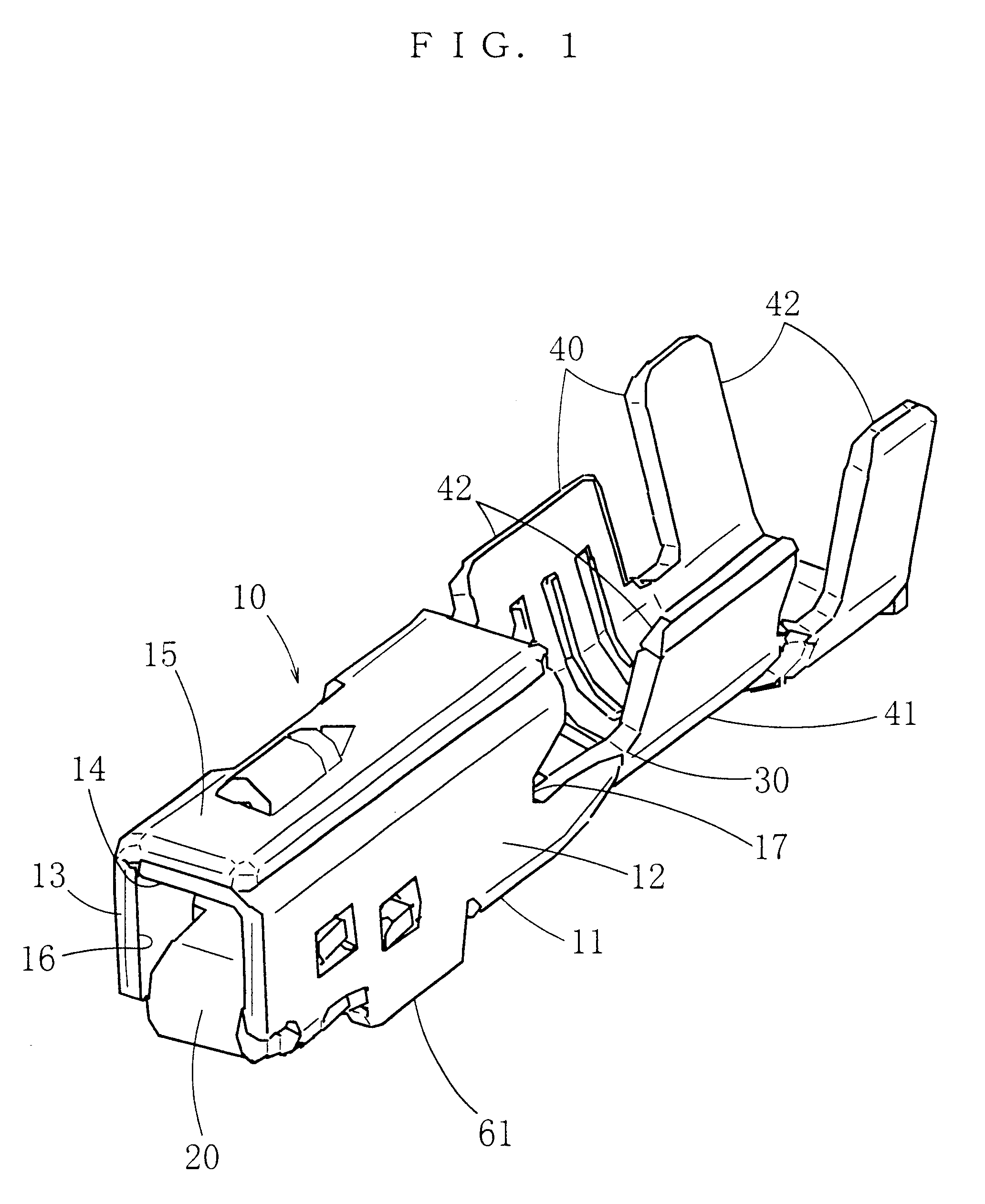
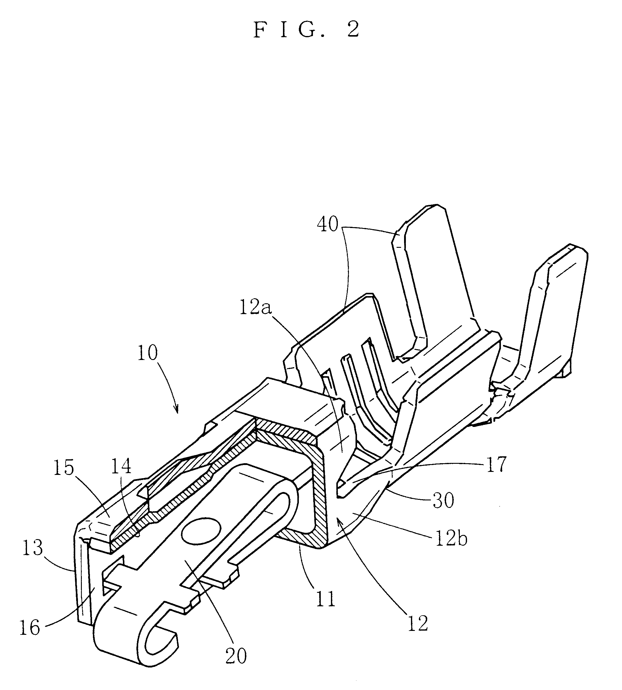
In the following, some embodiments of the present invention will be described with reference to the attached drawings. FIG. 1 through FIG. 4 show an embodiment of the female crimp terminal.

This female crimp terminal comprises a tubular body 10 into which a male terminal is fitted through a front opening 16 thereof, and a leaf spring 20 being located inside the body 10. The body 10 has a bottom wall 11, side walls 12, 13 rising from both ends, in the width direction, of the bottom wall 11, and upper walls 14, 15 extending sidewise from the upper ends of the side walls 12, 13. An opening 16 is formed by the walls 11 through 15 at the front end. In the case of the present embodiment, the body 10 is formed by folding a piece of plate. The first upper wall 14 extends sidewise from the upper end of one side wall 12, and the second upper wall 15 extends sidewise from the upper end of the other side wall 13 and overlaps with the first upper wall 14 from above. The present invention includes...


PUM


Abstract

A female crimp terminal includes a tubular body, a leaf spring contact inside the body and integrally extending from the front part of the body, a neck having a U shape when seen in the longitudinal direction and integrally extending from the lower parts of both side walls and the bottom wall at the rear end of the body, and a barrel having a U shape when seen in the longitudinal direction, integrally extending from the neck and having retainers extending upward high above the neck. A notch is made in a rear edge of each side wall from the rear end of the body so as to divide the side wall into an upper part and a lower part. This isolates crimping forces of the barrel from the tubular body which houses the leaf spring contact.

Description

1. Field of the InventionThe present invention belongs to a technical field of female crimp terminals to be fitted in housings of female connectors and relates to measures to prevent the body of a female crimp terminal from deformation.2. Related ArtA female crimp terminal is known, wherein a leaf spring is provided inside a tubular body into which a male terminal is inserted through a front opening of the tubular body, and the body is integrally provided with a barrel with a neck between the body and the barrel. In the case of the female crimp terminal that is disclosed by Japanese Patent unexamined publication gazette Heisei 9-147950, the body comprises a bottom wall, side walls rising from both ends, in the width direction, of the bottom wall, and upper walls extending sidewise from the upper ends of the side walls. The neck is formed approximately into a U shape when seen in the front-rear or longitudinal direction, and is integrally formed on the lower parts of both side walls ...

Claims


Application Information

Patent Timeline
Patent Type & Authority Patents(United States)
IPC IPC(8): H01R13/187H01R13/15H01R13/11H01R4/18
CPCH01R13/187H01R13/114H01R13/11
Inventor CHEN, PING
Owner JST MFG CO LTD
Why Eureka
Try Eureka