Cable rack mounted cable puller and installation system

a cable rack and cable puller technology, applied in the direction of electric cable installation, thin material handling, lifting devices, etc., can solve the problems of difficult utilization of cable racks, damage to building structures, and not designed to be securely mounted, so as to achieve efficient removal/installation of cables

Inactive Publication Date: 2003-03-18
SCHAFER RICHARD C
View PDF11 Cites 56 Cited by
  • Summary
  • Abstract
  • Description
  • Claims
  • Application Information

AI Technical Summary

Benefits of technology

In view of the foregoing disadvantages inherent in the known types of cable puller/installer devices, now present in the prior art, the present invention provides a new cable rack mounted

Problems solved by technology

The main problem with conventional cable puller/installer devices is they are not designed to be securely mounted to an open cable rack and often times require more than one individual to operate.
A further problem with conventional cable puller/installer devices is that they are comprised of a relatively large size making them difficult to utilize upon cable racks.
A further problem with conventional cable puller/installer devices is that they require the usage of anchor holes which damage the building str

Method used


Image

  • Cable rack mounted cable puller and installation system
  • Cable rack mounted cable puller and installation system
  • Cable rack mounted cable puller and installation system

Examples


Embodiment Construction

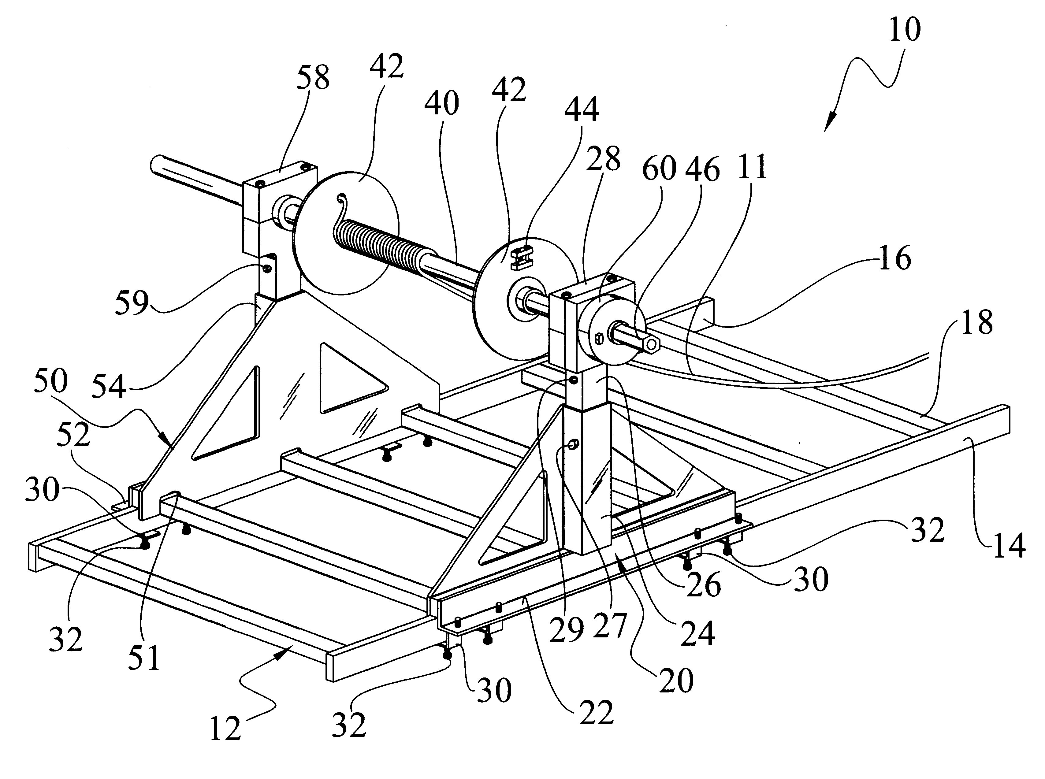
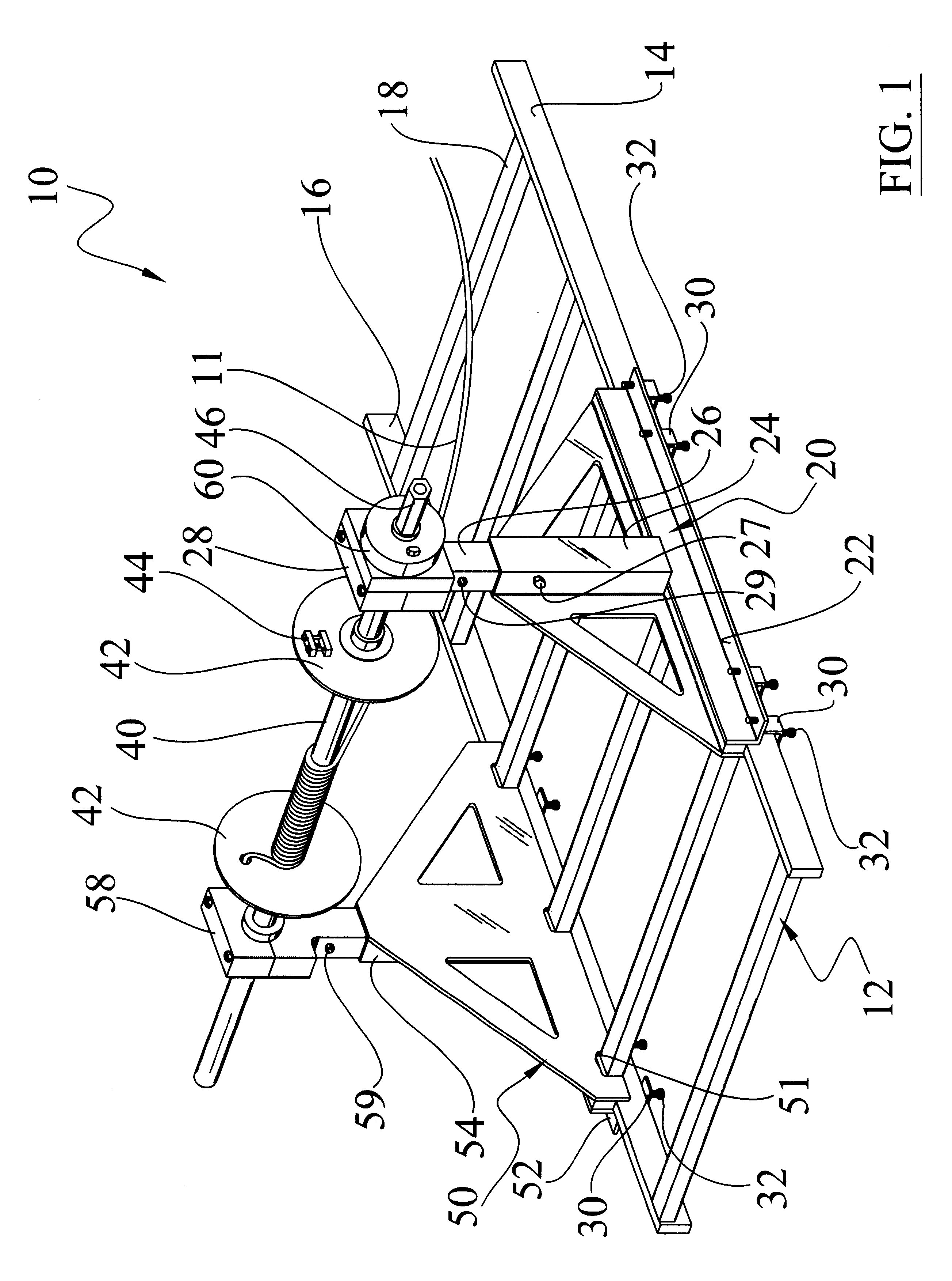
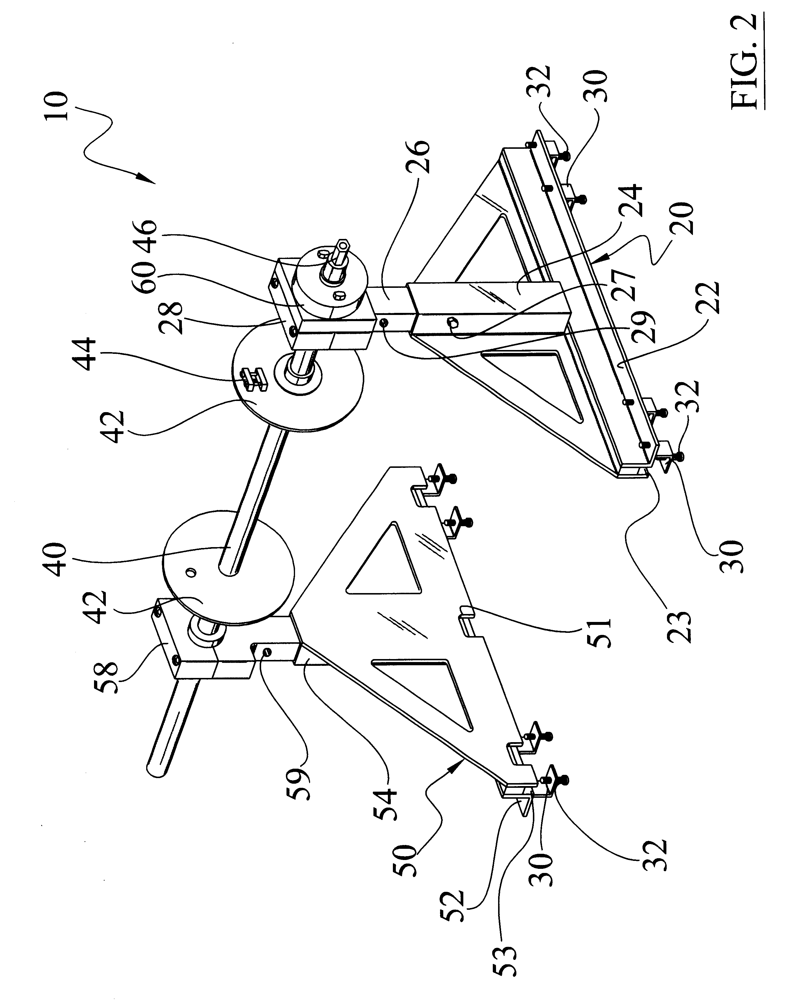
Turning now descriptively to the drawings, in which similar reference characters denote similar elements throughout the several views, FIGS. 1 through 6 illustrate a cable rack mounted cable puller and installation system 10, which comprises a first support frame 20 attachable to a first rail 14 upon a cable rack 12, and a second support frame 50 attachable to a second rail 16 upon the cable rack 12. A shaft 40 is rotatably supported between the upper portions of the support frames 20, 50 to receive a length of cable. A plurality of securing brackets 30 are pivotally attached to a base of the support frames 20, 50 to selectively surround the rails. A plurality of securing fasteners 32 within the securing brackets 30 allow for tightening of the support frames 20, 50 to the rails 14, 16. A coupler 46 is attached to an end of the shaft 40 for connecting a powered tool thereto to drive the shaft 40 for pulling or dispensing cable 11. The support frames 20, 50 are preferably comprised of...


PUM


Abstract

A cable rack mounted cable puller and installation system for removably attaching to a cable rack and efficiently removing/installing cable upon the cable rack. The cable rack mounted cable puller and installation system includes a first support frame attachable to a first rail upon a cable rack, and a second support frame attachable to a second rail upon the cable rack. A shaft is rotatably supported between the upper portions of the support frames to receive a length of cable. A plurality of securing brackets are pivotally attached to a base of the support frames to selectively surround the rails. A plurality of securing fasteners within the securing brackets allow for tightening of the support frames to the rails. A coupler is attached to an end of the shaft for connecting a powered tool thereto to drive the shaft for pulling or dispensing cable. The support frames are preferably comprised of an extendable structure for accommodating cables positioned at various heights. A clutch device is preferably attached to one of the support frames for preventing a reverse rotation of the shaft during operation thereof.

Description

CROSS REFERENCE TO RELATED APPLICATIONSNot applicable to this applicationSTATEMENT REGARDING FEDERALLY SPONSORED RESEARCH OR DEVELOPMENTNot applicable to this applicationBACKGROUND OF THE INVENTION1. Field of the InventionThe present invention relates generally to cable puller / installer apparatuses and more specifically it relates to a cable rack mounted cable puller and installation system for removably attaching to a cable rack and efficiently removing / installing cable upon the cable rack.Telecommunication locations within buildings often times utilize lengths of open cable racks to support a plurality of cables. FIG. 1 illustrates a conventional cable rack 12 which the present invention is suitable for usage upon. The cables may be comprised of various structures such as coaxial, fiber optic, DC power, twisted pair and various other types of cables. It can be difficult removing and installing elongate cables within a telecommunications environment because of the difficult locatio...

Claims


Application Information

Patent Timeline
IPC IPC(8): B65H49/00B65H54/553B65H49/32B65H54/40
CPCB65H49/32B65H54/553B65H49/325
Inventor SCHAFER, RICHARD C.
Owner SCHAFER RICHARD C
Why Eureka
Try Eureka