Bulkhead light fitting and lighting method

a technology for bulbheads and light fittings, applied in lighting and heating apparatus, lighting support devices, lighting applications, etc., can solve the problems of expensive repairs, damage or breakage of spa lights, and damage to spa walls, etc., and achieve the effect of reducing or eliminating the chance of light shade damag

Active Publication Date: 2015-05-14
CUSTOM MOLDED PROD
View PDF5 Cites 0 Cited by
  • Summary
  • Abstract
  • Description
  • Claims
  • Application Information

AI Technical Summary

Benefits of technology

[0009]Currently, lights attached to the outside walls of spas, spa walls, and / or spa shells risk being damaged or broken both during normal spa use and during the shipping and installation of the spa. With the permanently installed lights that are the current state of the art, this can mean expensive repairs. As such, the current state of the art is to use small lighting fixtures and / or no or small light shades. The present invention provides for a relatively low profile light having a mounting feature to which light shades can be removably attached. This provides at least four advantages. First, this allows the use of larger light shades as the light shades can be mounted on the spa after the spa has been shipped and installed, thus reducing shipping and installation damage. Second, the low profile of the light fixture without the light shade attached allows a more efficient shipping and installation process as the light fixture does not get in the way of shipping or installation and may even provide for a smaller shipping container. Third, as the light shade is replaceable, the user can replace the light shade if damaged or broken, or at the user's desire if a different aesthetic or functional light shade design is desired. Fourth, the spa manufacturer can make larger light shades and light fixtures that are more appropriate to the size of the spa, especially for larger spas.
[0013]The lens or light diffuser allows the transmission of light from the light source to the exterior of the spa. In a one piece embodiment of the base component, the lens or light diffuser is formed as part of the mounting support, preferably located as a generally central portion of the mounting support, and acts as the closed second end of the body. In a two piece embodiment of the base component, the lens or light diffuser, or at least a portion of the lens or light diffuser, is a separate component that is mounted within a central hole through the mounting support, the central hole being generally coextensive with and leading to the cylindrical interior of the body, with the lens or light diffuser, or the portion of the lens or light diffuser, cooperating with the open second end of the body so as to effectively close the open second end when the lens or light diffuser, or the portion of the lens or light diffuser, is installed.
[0019]If the base component is attached to the spa wall at the manufacturing location, the spa can be shipped, moved, and installed without fear of breaking the light shade. After the spa is installed, the light shade can be mounted onto the mounting support. If the base component is attached to the spa wall after the spa has been installed, the light shade can be mounted onto the mounting support at the time of installation. No matter when the base component is installed on the spa wall, the light shade can be easily replaced without disassembling the invention or the spa. Additionally, if a user decides to change the light shade, this can be easily done without disassembling the spa. Further, with the two piece embodiment of the base component, the light source can be easily replaced from the exterior of the spa by removing the light shade and removing the lens or light diffuser component, which will include removing the light clip connector, the light clip, and the light source.
[0021]One feature of the invention is that the base component is securely attached to the spa and is located generally flush or nearly flush with the spa wall exterior, while the light shade, which often extends outwardly from the spa wall, is removable and replaceable. As such, the spa can be shipped, moved, and installed without the light shade, thereby reducing or eliminating the chance that the light shade will be damaged during such shipping, moving, or installing. The light shade also can be replaced if broken without replacing the entire lighting system. Further, the user can select and install any of a number of different light shades at the user's desire so as to customize the spa.

Problems solved by technology

Currently, lights attached to the outside walls of spas, spa walls, and / or spa shells risk being damaged or broken both during normal spa use and during the shipping and installation of the spa.
With the permanently installed lights that are the current state of the art, this can mean expensive repairs.
Second, the low profile of the light fixture without the light shade attached allows a more efficient shipping and installation process as the light fixture does not get in the way of shipping or installation and may even provide for a smaller shipping container.
Third, as the light shade is replaceable, the user can replace the light shade if damaged or broken, or at the user's desire if a different aesthetic or functional light shade design is desired.

Method used


Image

  • Bulkhead light fitting and lighting method
  • Bulkhead light fitting and lighting method
  • Bulkhead light fitting and lighting method

Examples


Embodiment Construction

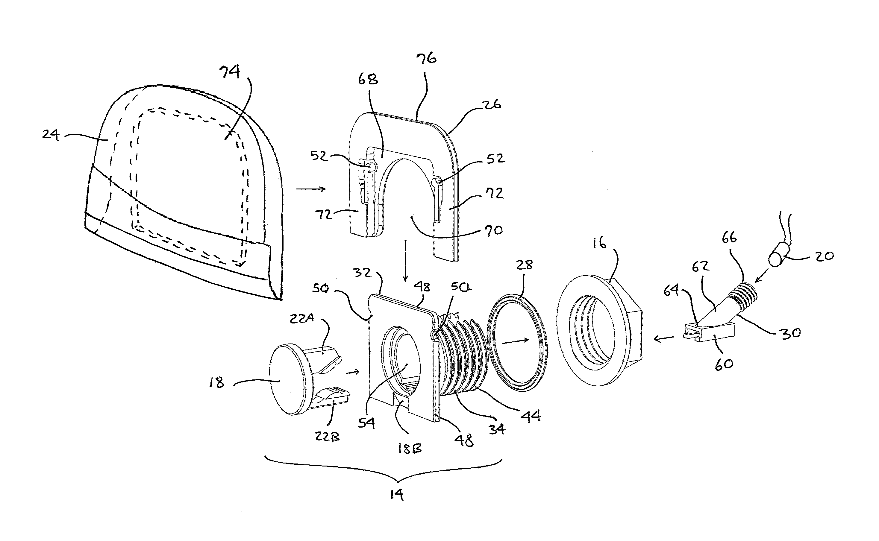
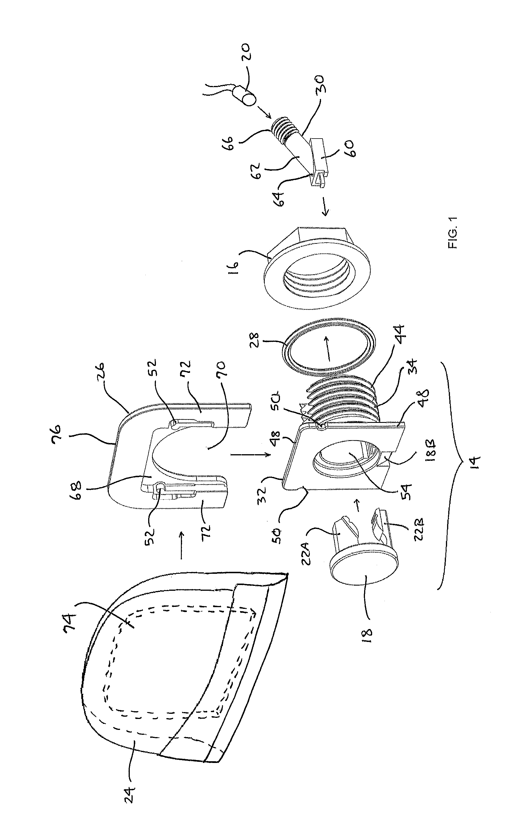
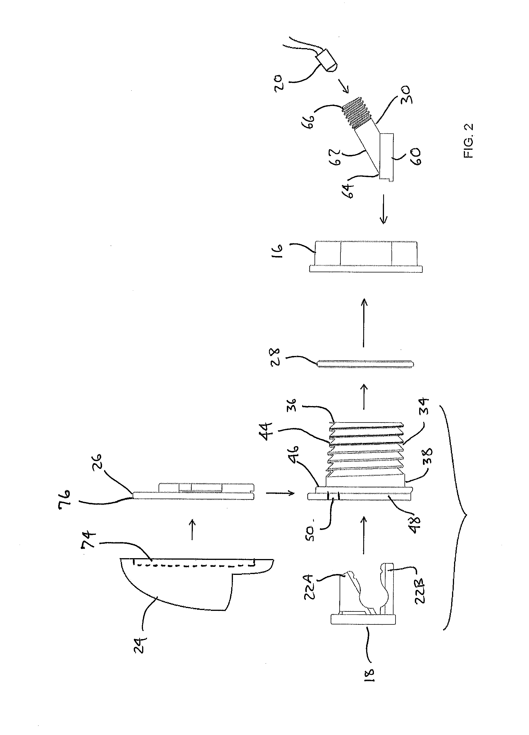
[0034]Illustrative embodiments of a bulkhead light fitting 10 according to the present invention are shown in FIGS. 1 through 11. FIG. 1 is an exploded perspective view of an embodiment of the invention and FIG. 2 is an exploded side view of the embodiment shown in FIG. 1, with a two-piece base component 14. FIG. 3 is a perspective front view of an embodiment of the invention shown in unexploded form and FIG. 4 is a side view of an embodiment shown in FIG. 3, installed on a spa wall 12. FIG. 5 is a front view of an embodiment of the invention, in a simplified schematic form. FIG. 6 is a rear view of an embodiment of the invention and FIG. 7 is a top view of an embodiment of the invention, installed on a spa wall 12. FIG. 8 is a sectional side view of an embodiment of the invention along section line A-A of FIG. 5, with a two-piece base component 14. FIG. 9 is a sectional side view of the embodiment of the invention of FIG. 8 in greater detail. FIG. 10 is a sectional side view of an ...


PUM

PropertyMeasurementUnit
transparentaaaaaaaaaa
semi-transparentaaaaaaaaaa
transmissionaaaaaaaaaa

Abstract

A light fitting and method for illuminating the exterior of spas, swimming pools, hot tubs, garden baths, and the like, the light fitting having a base component mounted through a spa wall; a lens or light diffuser on an exterior end of the base component; a light source on, in, or proximal to an interior end of the base component; a light clip for retaining the light source on, in, or proximal to the base component; a light shade located on or proximal to the exterior end of the base component; and an attachment plate for attaching the light shade onto the base component via a mounting support; the base component having a cylindrical hollow body having a hollow interior, a first end located within the spa wall, and a second end located proximal to the spa wall, with the mounting support being attached to the cylindrical hollow body.

Description

BACKGROUND OF THE INVENTION[0001]1. Technical Field[0002]The present invention generally is in the field of lighting devices and methods for spas, swimming pools, hot tubs, garden baths, and the like. The present invention more particularly is in the field of lighting devices and methods for illuminating the exterior of and / or the area surrounding spas, swimming pools, hot tubs, garden baths, and the like. The present invention more particularly also is in the field of lighting devices and methods for generating aesthetically pleasing light on and around spas, swimming pools, hot tubs, garden baths, and the like. The present invention more particularly also is in the field of lighting devices and lighting methods having a permanent or semi-permanent lighting base with removable and replaceable covers and shades having different aesthetic designs and shapes.[0003]2. Prior Art[0004]Few applications derive more benefit from the addition of aesthetically pleasing and / or safety lighting ...

Claims


Application Information

Patent Timeline
Patent Type & Authority Applications(United States)
IPC IPC(8): F21V17/10F21V13/02F21V1/00F21S8/00F21V21/088
CPCF21V17/10F21S8/00F21V13/02F21V1/00F21V21/088F21S8/02F21V3/00F21V17/002F21V21/04F21W2131/401Y10T29/49948
Inventor WALKER, VICTOR L.PUGLIESE, JR., ANGELO V.
Owner CUSTOM MOLDED PROD
Why Eureka
Try Eureka