Magnetic fastening system and method for change parts

a technology of magnetic fastening and change parts, which is applied in the direction of transportation and packaging, manufacturing tools, liquid handling, etc., can solve the problems of inability to remove, damage the fastener, and the machine may inadvertently come into conta

Inactive Publication Date: 2016-12-20
PNEUMATIC SCALE CORP
View PDF8 Cites 1 Cited by
  • Summary
  • Abstract
  • Description
  • Claims
  • Application Information

AI Technical Summary

Benefits of technology

[0008]It is a further object of exemplary embodiments to provide a fastening method and system which requires less maintenance and which can be used in a filling or capper machine to removably attach interchangeable components, such as rotary stars, guides, and change parts.
[0009]It is a further object of exemplary embodiments to provide a fastening method and system which is more durable and which can be used repeatedly in a filling or capper machine to removably attach interchangeable components, such as rotary stars, guides, and change parts without significant impact from wear and tear.
[0011]The foregoing objects are accomplished in an exemplary embodiment by a system which uses interchangeable components with one or more mechanically locking fasteners and one or more pairs of magnets which are out of alignment with one another when the mechanically locking fasteners are in an unlocked position and which urge the interchangeable component to move toward the mechanically locked position, thereby engaging a mechanically locking fasteners. Thus the fastening system achieves the above stated objectives, eliminates difficulties encountered in the use of prior methods, solves problems, and attains the desirable results described herein.

Problems solved by technology

In addition to requiring tools to remove the interchangeable components, any fastener which is used in filling and capper machines may inadvertently come into contact with the material which is being introduced into the containers.
Such material may be corrosive or may otherwise damage the fasteners, or make them difficult or impossible to remove.
Finally, fasteners such as bolts often have relatively fine features, such as threading, which wear or otherwise become damaged over time.
These factors each tend to increase the manufacturing down time because of the time it takes to switch out the interchangeable components in order to change a line from being used with one container type to being used with another, or to clean or replace an interchangeable component or worn out fasteners.

Method used


Image

  • Magnetic fastening system and method for change parts
  • Magnetic fastening system and method for change parts
  • Magnetic fastening system and method for change parts

Examples


Embodiment Construction

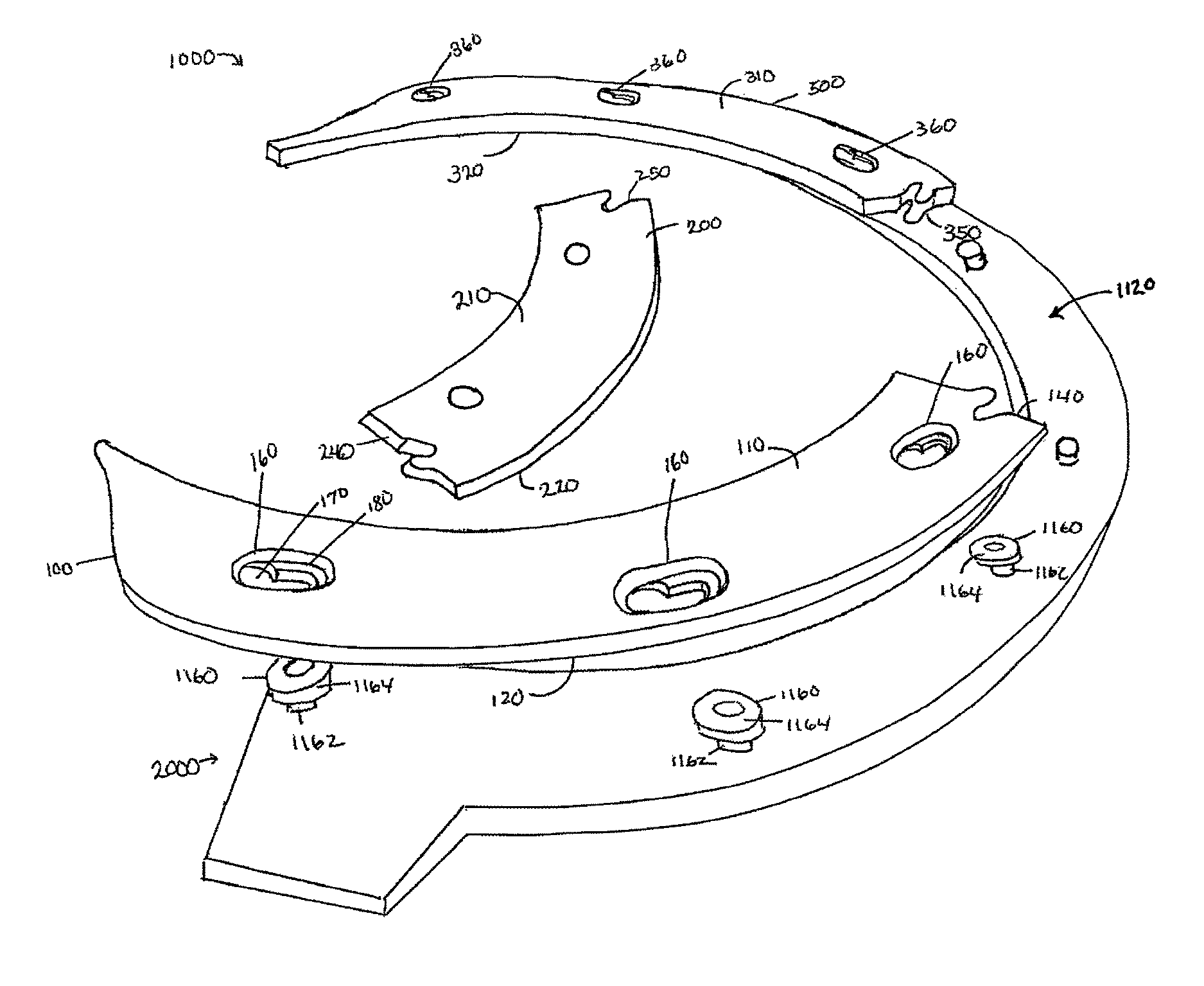
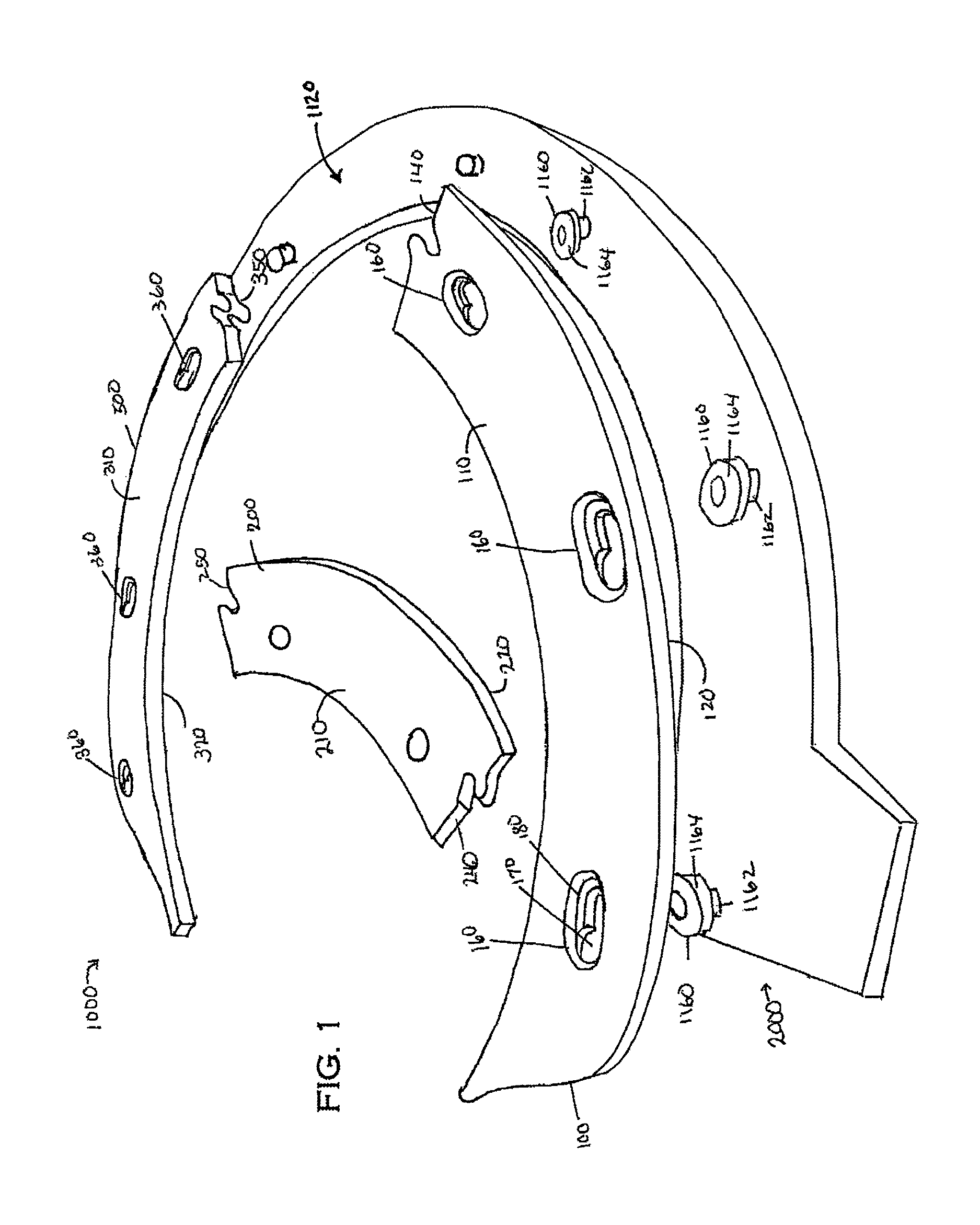
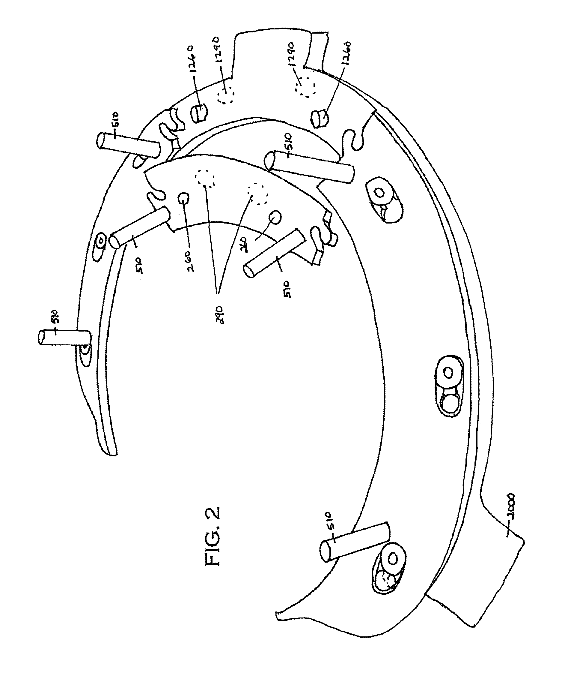
[0006]It is an object of exemplary embodiments to provide a fastening method and system which can be used in a filling or capper machine to removably attach interchangeable components such as rotary stars, guides, and other change parts without using tools.

[0007]It is a further object of exemplary embodiments to provide a fastening method and system which can be used in a filling or capper machine to removably attach interchangeable components, such as rotary stars, guides, and other change parts, using magnets to align the parts.

[0008]It is a further object of exemplary embodiments to provide a fastening method and system which requires less maintenance and which can be used in a filling or capper machine to removably attach interchangeable components, such as rotary stars, guides, and change parts.

[0009]It is a further object of exemplary embodiments to provide a fastening method and system which is more durable and which can be used repeatedly in a filling or capper machine to re...


PUM

PropertyMeasurementUnit
sizeaaaaaaaaaa
shapeaaaaaaaaaa
corrosiveaaaaaaaaaa

Abstract

A fastening system and method to removably attach change part components to a capping or filling machine in order to adapt a general purpose machine for use with a specific size or shape container. The fastening system and method uses magnetic forces to pull component parts into alignment and to interlock portions of interchangeable components. In addition, a blocking component is interposed between two other interchangeable component parts or within mushroom slots, securing the components in place, aided by biasing magnets. This system and method relies on a combination of mechanical and magnetic forces by using mechanical forces to reinforce or supplement biasing magnetic forces, and vice versa, creating a durable connection that will withstand the rigors of the filling and capping process, yet which is simple to assemble and disassemble without tools. The less intricate component parts are less prone to damage during assembly, use or disassembly.

Description

REFERENCE TO RELATED APPLICATIONS[0001]This application is a continuation of U.S. patent application Ser. No. 13 / 459,266 filed Apr. 30, 2012, which application claims benefit under 35 U.S.C. §119(e) of U.S. Provisional Application 61 / 480,360 filed Apr. 28, 2011, the disclosures of which are incorporated herein by reference in their entirety.TECHNICAL FIELD[0002]This invention relates generally to machines used in the manufacturing process to fill and cap containers. Specifically, this invention relates to a method and system for fastening change parts, rotary stars, guides, and other such interchangeable or removable components to relatively permanent portions of such filling and capper machines.BACKGROUND ART[0003]Filling and capper machines are well known in the industry. Exemplary machines include those described in U.S. Pat. Nos. 6,065,508 and 6,105,343, the entirety of which are incorporated herein by reference. Filling and capper machines, particularly rotary filling and cappe...

Claims


Application Information

Patent Timeline
Patent Type & Authority Patents(United States)
IPC IPC(8): B25B27/14B65B59/04B67C3/22B23P19/04
CPCB65B59/04B67C3/22B23P19/04Y10T408/56343F16B21/09F16B2200/83B25B27/14B23Q3/062
Inventor CELLI, JR., PAULTOTH, JOHNTHOMPSON, ROBINREEVES, PATRICK
Owner PNEUMATIC SCALE CORP
Why Eureka
Try Eureka