Fast charger for high capacity batteries

a high-capacity battery and fast charging technology, applied in the direction of charge maintainance charging/discharging, sustainable buildings, transportation and packaging, etc., can solve the problems of increased capital expenditure, significant inconvenience of users of high-capacity batteries, and loss of employee tim

Inactive Publication Date: 2005-03-03
AKER WADE POWER TECH
View PDF12 Cites 124 Cited by
  • Summary
  • Abstract
  • Description
  • Claims
  • Application Information

AI Technical Summary

Benefits of technology

Sizing the output inductor properly is an important aspect of the invention. In general, the requirements for filtering the fast charger output are dictated by the need to minimize heating of the battery being charged. Minimizing ripple current delivered to the battery minimizes undesirable heating. However, the amount of ripple current that the battery can tolerate depends on the type of battery being charged. Typically, flooded lead acid storage batteries are able to tolerate a somewhat “dirty” charging input, e.g., ripple current of up to 10 percent vs. peak current is acceptable. However, sealed lead acid storage batteries require a very well-filtered DC current input for charging; if heating causes off-gassing, an explosion can be the result. However, sealed storage batteries have a number of desirable attributes, such as lack of odor, low maintenance, and the sealed construction eliminates periodic watering, corrosive acid fumes and spills. Therefore, it is an advantage of the invention that the fast charger design is adaptable to these quite different requirements by adjustment of the output filter specifications.
that the fast charger design is adaptable to these quite different requirements by adjustment of the output filter specifications.
In addition, thermal management of the batteries is a variable. In many uses, a great deal of demand is placed on the battery. Thus the battery may arrive at the fast charger already quite hot. In the case of sealed batteries, the need to minimize heating is exacerbated. Cooling means such as fans may be deployed to cool the depleted battery.
Battery temperature is an important parameter. Batteries that come in for charging and are at a temperature in excess of 125° F. cannot be effectively fast charged, and must be cooled to suitable temperature. It is important that batteries are not in excess of 115° F. when beginning their fast charge, and preferably the battery temperature will be <100° F. at the inception of fast charging, because there will be a temperature rise of about 15° F. over the 30-90% SOC charge cycle with the fast charger of the invention. If the battery temperature is greater than 130° F., the battery should not be charged at any rate (standard rate or fast rate).
In heavy use applications, where the batteries are being discharged in use at a high rate, heating of the battery may be minimized by deploying a fan on the vehicle or battery cover, blowing over the battery interconnects to continuously remove heat from the battery.
Another thermal management approach is to use copper inserts in the battery posts and cell interconnects. Copper parts have {fraction (1 / 12)} the electrical resistance and 12 times the thermal conductivity of parts made from an equivalent mass of lead. Selection of copper parts results in less heat being generated in the battery and more heat being conducted away from the battery. The combination of both fans and copper is extremely effective in minimizing battery heating.

Problems solved by technology

Previously, with conventional chargers, the time required for recharging has significantly inconvenienced users of high capacity batteries when the battery-powered equipment needs to remain in continuous service.
Therefore conventional charging results in a number of disadvantages for the industrial user: loss of employee time for non-productive tasks; safety issues due to additional truck travel away from normal work areas within the plant and the need to handle heavy batteries; increased capital expenditures for the two or more batteries required per piece of equipment; and operation of battery-powered equipment at a low SOC, hence higher current, resulting in increased vehicle maintenance.
A fast charger in the garage would bring back up the family auto after the commute home to allow a drive to the mall or soccer field in the evening, which may otherwise not be possible in the absence of fast charging.
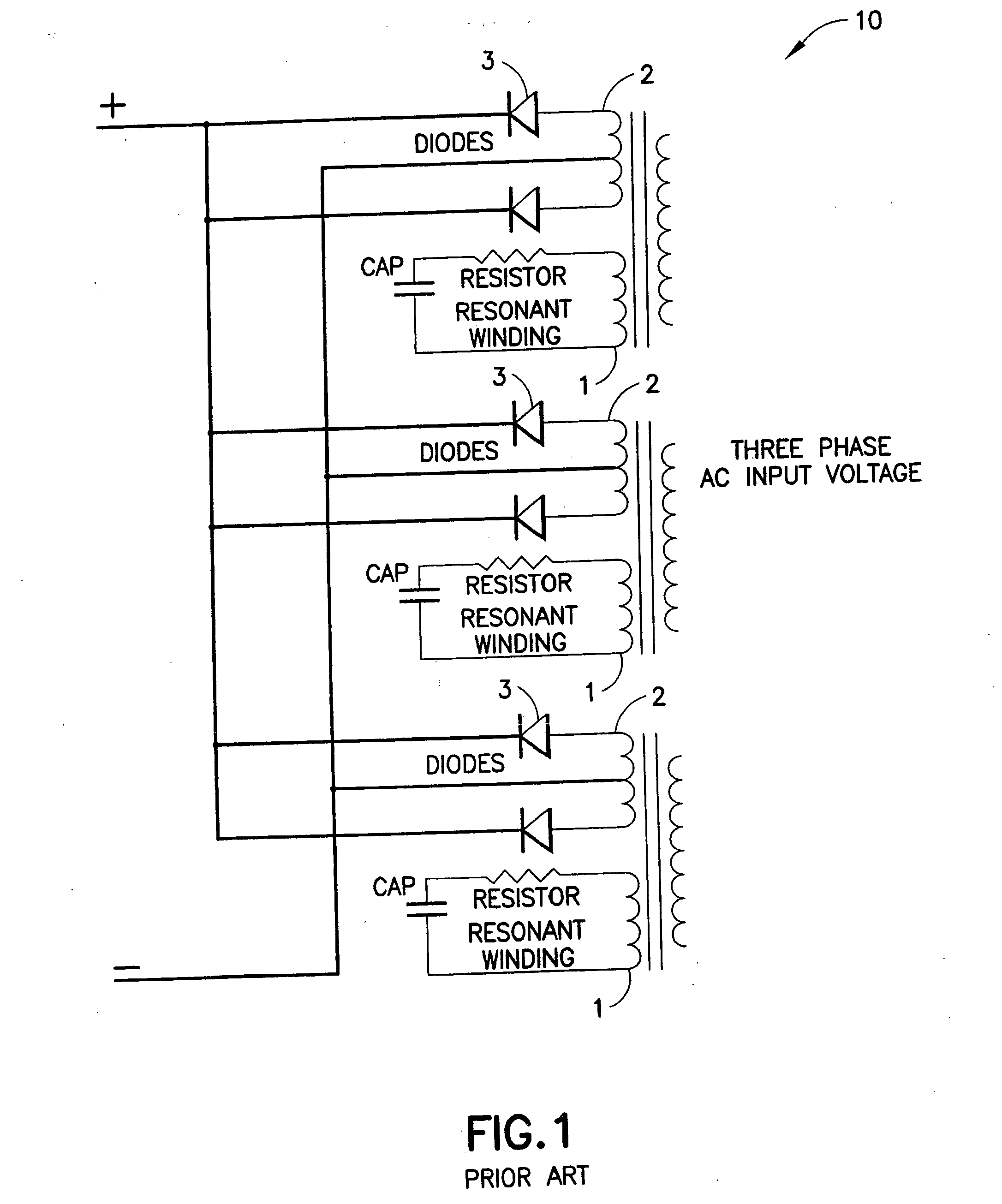
The ferro-resonant style charger described above has a number of inherent deficiencies that limit its practical utility.
Another inherent problem is the different Ampere-hour ratings of various batteries.
A manual change is required to tune the ferro-resonant charger to accommodate the various Ampere-hour ratings, thereby increasing the time and complexity of the charging operation.
In addition, the selection range is limited for such modifications to accommodate different Ahr battery ratings.
The limited control of output voltage that is characteristic of ferro-resonant chargers also prevents maximum charge rates from being achieved throughout the entire charge cycle.
Further, ferro-resonant chargers are unable to take significant corrective action to compensate for supply voltage variations.
This AC component causes extra heating within the battery and presents a thermal management issue that is of particular concern in the application of ferro-resonant chargers to high rate charging.
These various shortcomings cause the ferro-resonant charger to be inefficient in operation, inflexible in voltage output, and non-optimal in its charging profile.
This circumstance requires the inductor to be large and expensive.
If a smaller, less costly inductor is employed, the additional 360 Hertz AC ripple component superimposed on the DC voltage from the charger will cause heating within the battery load and degrade the power factor of the charger.
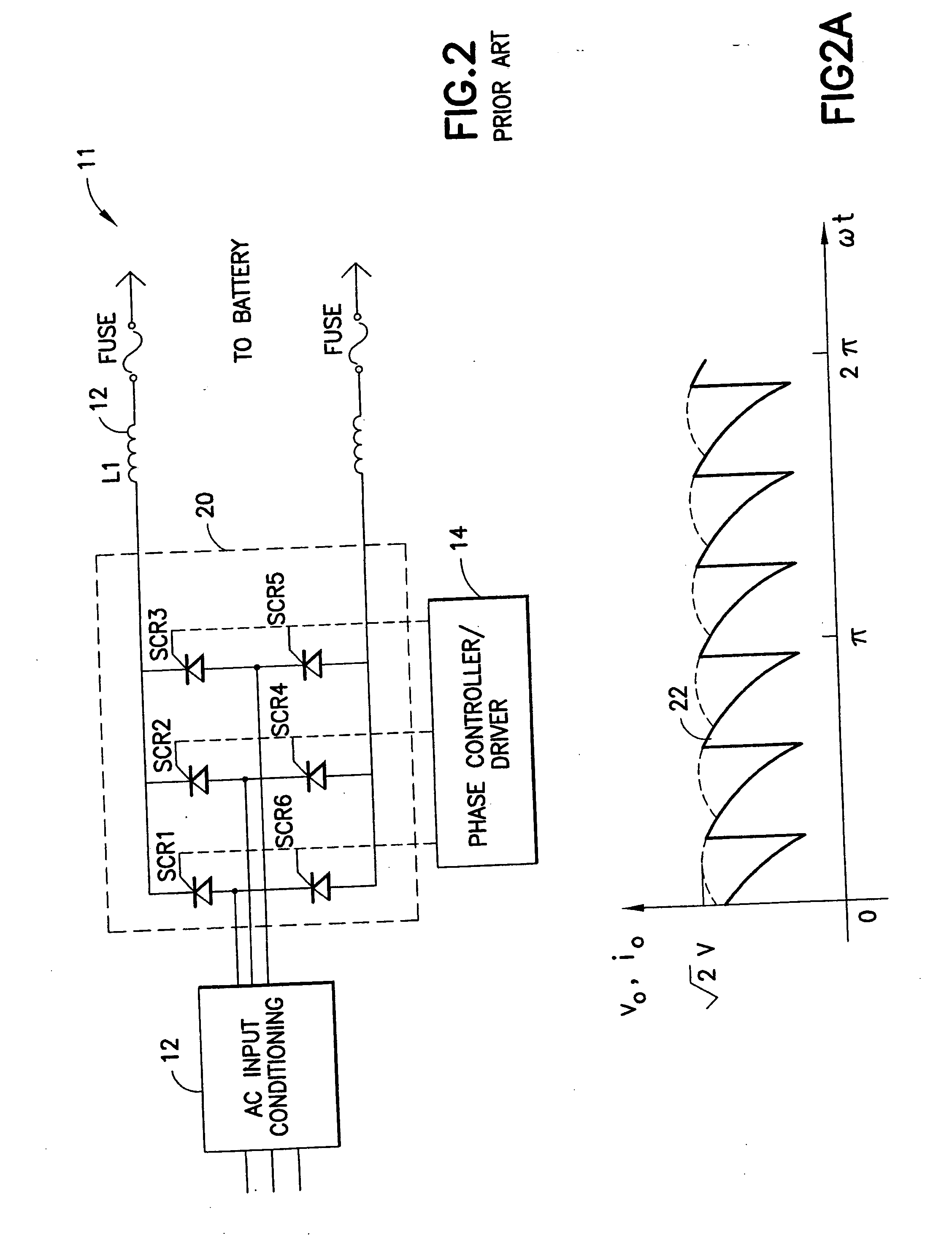
As a result, the power factor of such charger is adversely affected when the charger is used to charge lower voltage batteries. FIG. 2A depicts the SCR switch matrix phase control duty cycle, and shows that for lower voltage batteries, the SCR switch matrix phase control duty cycle must be reduced (see waveform 22) and this reduction in turn greatly degrades power factor.
The resultant low power factor results in high currents being drawn from the AC input line in proportion to the true power being delivered to the battery.
SCR-based chargers experience both steady state and switching losses, which degrade their overall efficiency.
Furthermore, SCR commutation requirements dictate higher current VA ratings for other circuit components, and SCR recovery times significantly slow down the maximum switching frequencies obtainable.
The drive control circuitry for the SCR switch matrix is complex and expensive because there are multiple SCRs to control (e.g., six in the illustrative system shown in FIG. 2).
Finally, the input three-phase AC supply must be connected in the correct sequence in order to prevent phase reversal, since phase reversal would result in an SCR switch matrix error.
However, problems would remain in achieving the power levels necessary for very high capacity batteries (>600 Ahrs capacity) required in many industrial applications.
The full bridge circuit employs 4 switches, and, when high voltages are switched, the circuit is susceptible to problems relating to the slower switching speed characteristics of high voltage devices and heat generation.
Additionally, transients on the line voltage may destroy the switches, since they are not well isolated.
However, design of a buck regulator system for fast charging high capacity batteries has not been achieved and faces a number of technical challenges that have heretofore remained unsolved.
Relative to switching requirements, switches that switch high currents at high frequencies (e.g., greater than about 5000 Hz) are characteristically associated with unacceptable heat generation, and switches that operate at lower frequencies would require unacceptably large and expensive filters.
In addition, the currents required for fast charging of high capacity batteries are very high, e.g., hundreds of Amperes, and thus introduce a myriad of problems relating to the electrolytic capacitors needed for the AC input rectifier circuitry.
For high capacity battery charging, these capacitors would have to be so large that their pulse current capability would be very low, e.g., on the order of about 30 A each, and they are less effective at high frequencies because they develop higher inductance under such conditions.
The resulting bus structure would be so large and inductive as to render the construction impractical.
Additionally, the use of such capacitors, whether of large size or of small size, results in a low power factor.
Faced with these problems, the art has been unable to achieve a truly viable fast charging technology.

Method used


Image

  • Fast charger for high capacity batteries
  • Fast charger for high capacity batteries
  • Fast charger for high capacity batteries

Examples


first embodiment

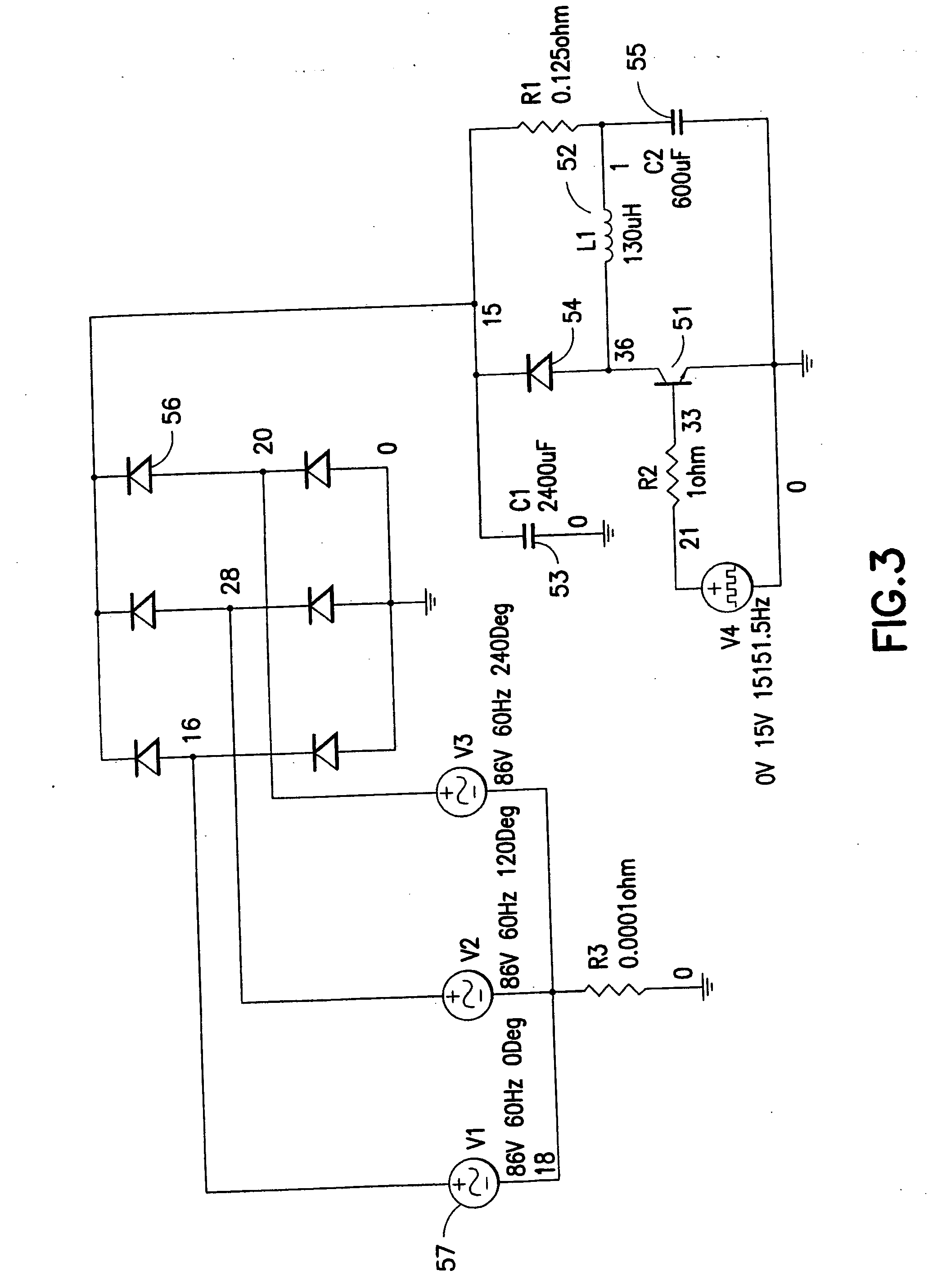
In a first embodiment, the pulse width modulation used to provide the output power is itself modulated in response to the 360 Hz rectified 3-phase AC input waveform. As the ripple from the 360 Hz rides largely unfiltered on the DC bus, the PWM duty cycle is synchronously varied in proportion and accordance with the AC ripple voltage. As the AC voltage increases, the PWM is decreased in order to accommodate the higher input voltage and is correspondingly increased when the AC voltage decreases in the 360 Hz DC bus ripple sinusoidal waveform. This is accomplished by continuously monitoring the output or input voltage ripple to the controller and adjusting the drive PWM on a pulse-by-pulse basis. As the voltage increases on the DC output of the converter, the PWM duty cycle is reduced and as the voltage decreases on the DC output the PWM duty cycle is increased. This effectively removes the 360 Hz AC ripple component on the DC bus input from the voltage output of the converter and prov...

second embodiment

In a second embodiment, a 15 kHz rate every pulse triggers an interrupt service routine (ISR). In this routine, the output voltage, VOUT, is read. If VOUT is too high the PWM is decremented by 1 and the ISR is terminated. If VOUT is at or below VOUTNOM desired the current is then measured. If the current is above 125% Imax the program immediately decrements the PWM and exits the ISR. If the current is below or equal to 125% of INOM the PWM Ramp delay is examined and if equal to zero the ramp delay count is reloaded and the PWM is decremented by one before exiting the ISR. If the ramp delay is not equal to zero, the ramp delay is decremented and the ISR exited. If the current is below a desired level the ramp is delayed and the ramp delay count must be zeroed before the PWM can be incremented. If the current is as desired, the ISR is exited immediately and no change in the PWM count is made.

FIG. 12 is a flow chart illustrating a second control technique for the fast charger of the in...

third embodiment

In a third embodiment, the output voltage and current are continuously monitored and prevented from exceeding desired values while at the same time allowing the passing of the 360 Hz AC ripple current and voltage, created by the input rectification process, by the use of one or both of the following techniques. The voltage and current values are filtered in an analog circuit which averages their value over the 360 Hz rectified input cycle and prevents control reaction to small variations within this 2.77 mS time frame. The PWM output circuit in the microprocessor is prevented from reacting to minor variations in the output voltage and current by numerical methods and / or limiting the adjustment frequency of its control response.

FIG. 14 is a flow chart illustrating a third control technique for the fast charger of the invention, and FIG. 15 is a software listing for the third control technique shown in FIG. 14.

As shown in the drawing of FIG. 14, *RDC is ramp delay count, CC is const...


PUM


Abstract

A highly efficient fast charger for high capacity batteries and methods for fast charging high capacity batteries. The fast charger preferably comprises a rectified AC input of single or preferably three phases, with an optional power factor corrected input, minimally filtered with high frequency, high ripple current capacitors, which is switched with a power switching circuit in the “buck” configuration into an inductor / capacitor output filter. Metallized film capacitors are employed, to minimize the rectified 360 Hertz AC component filtering while providing transient switch protection and ripple current requirements for the buck regulator, to provide a high current fast charger with substantially improved power factor. High power, high frequency switching with minimized output filter size provides a highly filtered DC output. The fast charger is adapted to be constructed in a modular design for simple maintenance.

Description

FIELD OF THE INVENTION This invention pertains to fast charging of high capacity batteries, in particular to an apparatus and electrical circuits for fast charging high capacity batteries, methods for battery charging, and methods and software for controlling the delivery of voltage and current to high capacity batteries during fast charging. BACKGROUND “Fast charging” refers herein to charging a battery at a rate of greater than 30 Amperes per 100 Ampere-hours (“Ahrs”) of battery capacity. A goal of fast charging is to bring the state of charge (“SOC”) of a battery from 30% to 80% of full charge in less than about 1.5 hours. Conventional battery chargers typically operate at charging rates that are at or below 20 A per 100 Ahrs of battery capacity, their charging rate decreases early in the charge cycle, and 8-12 hours may be required to restore a battery to full charge. Previously, with conventional chargers, the time required for recharging has significantly inconvenienced user...

Claims


Application Information

Patent Timeline
Patent Type & Authority Applications(United States)
IPC IPC(8): H02J7/00H02J7/02
CPCH02J7/0042H02J7/0047Y02B40/90H02J7/0075H02J7/022H02J7/0073H02J7/0071H02J7/0069H02J7/02H02J2207/20Y02B40/00H02J7/0048
Inventor AKER, JOHN F.WADE, JAMES R.
Owner AKER WADE POWER TECH
Why Eureka
Try Eureka