Inspection system and method

a technology of inspection system and inspection method, applied in the field of inspection system and method, can solve the problem that the inspection system should be self-contained, and achieve the effect of time-consuming and laborious inspection

Inactive Publication Date: 2003-03-25
ENVIROSIGHT
View PDF13 Cites 96 Cited by
  • Summary
  • Abstract
  • Description
  • Claims
  • Application Information

AI Technical Summary

Benefits of technology

The present invention provides for a quick and convenient approach to ascertain the condition of an inaccessible or uninhabitable area before initiating a more comprehensive inspection. More specifically, rather than physically entering the area to be inspected with a robotic or push camera, a self-contained, highly-maneuverable, hand-held inspection system is positioned with the area in its field of view and then is zoomed in to obtain an image at the desired magnification. Thus, the device obtains images of inaccessible or uninhabitable areas by maneuvering an imaging device and using its magnification capabilities rather than by physically entering the area.
Once the images are obtained, an analysis may be performed to determine whether problems such as cracks, blockage, and root infiltration exist. The images obtained preferably are in a readily-transmitted form, such as a bit-map, thereby allowing them to be transmitted for off-site analysis if need be. If no problem is detected, then the device can be moved quickly to another area to perform another inspection. On the other hand, if a problem is detected, a pipe crawler or other invasive type of inspection may be performed to obtain the details necessary to remedy the situation. This way, the time of setting up and operating a pipe crawler or similar device is not wasted on areas that are in acceptable condition.

Problems solved by technology

Second, the inspection system should be self-contained.

Method used


Image

  • Inspection system and method
  • Inspection system and method
  • Inspection system and method

Examples


Embodiment Construction

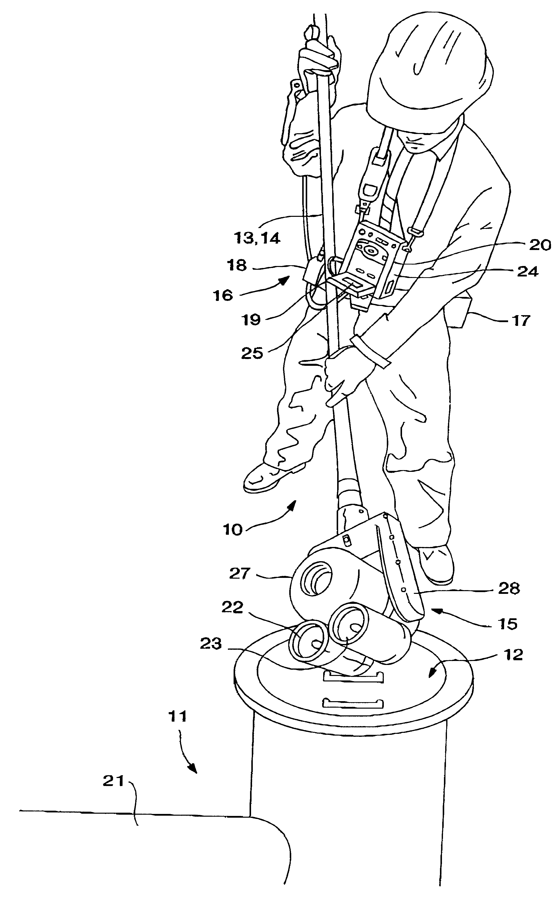
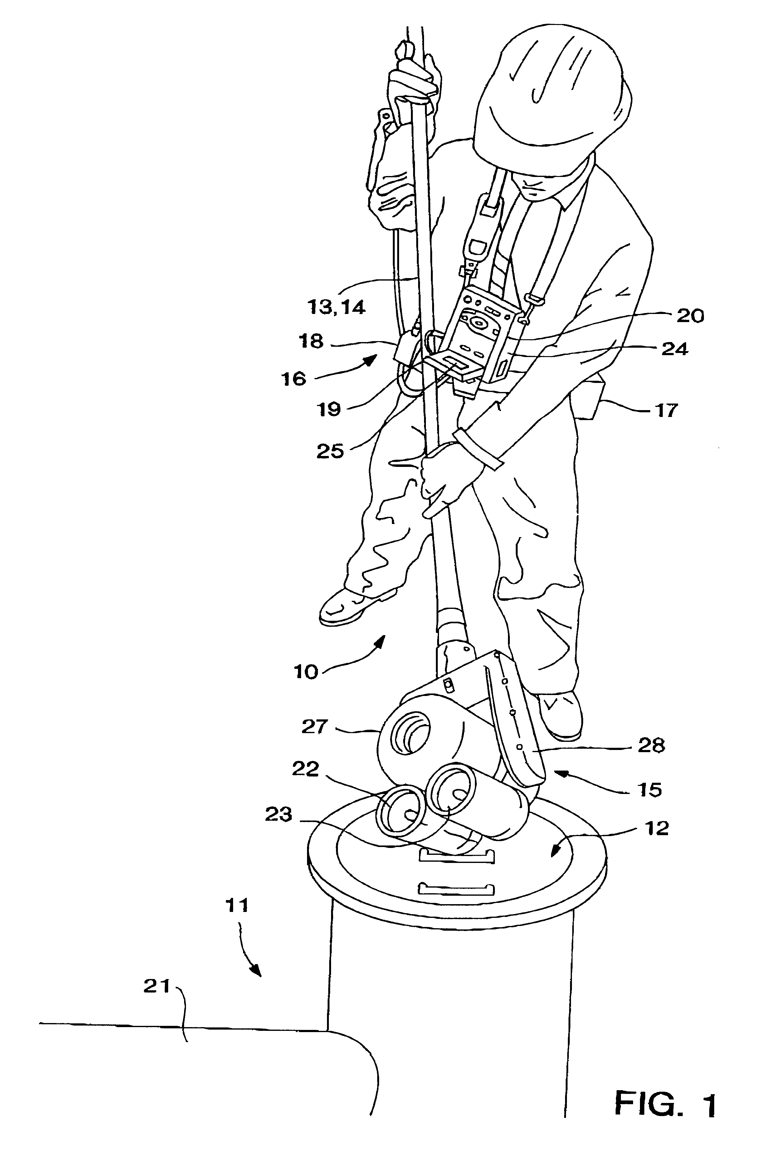
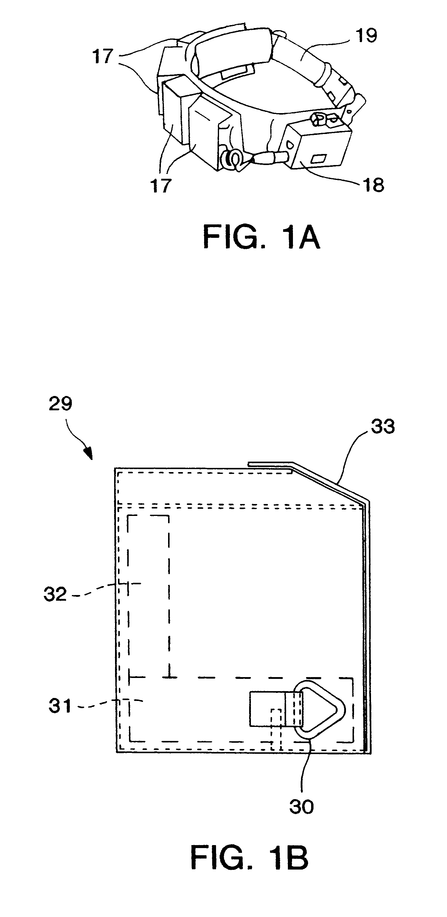
Referring to the drawings, FIG. 1 shows a user inspecting a storm or sewer pipe using a preferred embodiment of the inspection system 10 to ascertain whether a more comprehensive inspection is warranted. More specifically, using a positioning system 13, which, in this embodiment is a telescoping boom 14, the user lowers the imaging system 15 into a manhole 12. The user is wearing a support system 16 which in this embodiment comprises a power supply 17 and control functionality 18 worn on a belt 19, and monitoring and recording functionality 20 worn around the users neck. A detailed illustration of the belt 19 is provided in FIG. 1a. The components of the support system are described in greater with respect to FIGS. 2-5.

While observing a monitor 25, the user inserts the image system into the manhole 12. Imaging the interior of the manhole typically is performed in close proximity thereto A and thus at a low magnification level which provides a wide field of view. The user then would ...


PUM

PropertyMeasurementUnit
focal lengthaaaaaaaaaa
electricalaaaaaaaaaa

Abstract

A system comprises: (a) an imaging system having an imaging device for transmitting an electrical signal corresponding to an area being imaged, and magnification functionality adapted to magnify the imaged area; (b) a portable support system for supporting the imaging system having a power supply for supplying power to the imaging system, at least one controller for controlling the zooming functionality of the imaging device, and an image output device; and (c) a positioning system for positioning the imaging system independently of the support system; and a method of using the same which comprising: (a) positioning the imaging system independently of the support system such that a target area is in the field of view of said imaging system while at a first magnification level; (b) imaging the area at a second magnification level greater than the first magnification level; and (c) outputting an image of the area.

Description

The present invention relates generally to the inspection of areas which are hard-to-read, inaccessible or uninhabitable for humans. More specifically, the invention relates to the inspection of manholes and the lateral pipes radiating therefrom.It is often necessary to inspect areas under conditions which render them inaccessible or otherwise uninhabitable by humans over an extended period. These conditions include, for example, small confined spaces, lack of air / oxygen, presence of toxins, radioactivity, contamination, excessive dust, dirt and filth, and high noise levels. These conditions can be found in areas common to storm and sewer pipes, nuclear reactors and containments, fossil fuel plants and petrochemical refining facilities just to name a few. Although the need for inspection and the problems associated with these areas varies, the inconvenient and time-consuming nature of performing the inspection remains a constant.For illustrative purposes the inspection of storm and ...

Claims


Application Information

Patent Timeline
Patent Type & Authority Patents(United States)
IPC IPC(8): H04N7/18E03F7/12G01N21/954
CPCE03F7/12H04N7/183G01N21/954
Inventor DROST, JEFFREY D.MOONEY, DAVID J.SALVATI, JON R.
Owner ENVIROSIGHT
Why Eureka
Try Eureka