Inspection system and method

a technology of inspection system and inspection method, applied in the field of inspection system and method, can solve the problems of inconvenient and time-consuming nature of performing the initial inspection, affecting the quality of inspection results, and requiring a great deal of time to set up and operate, so as to achieve quick and convenient non-invasive and convenient positioning

Inactive Publication Date: 2004-08-19
ENVIROSIGHT
View PDF8 Cites 25 Cited by
  • Summary
  • Abstract
  • Description
  • Claims
  • Application Information

AI Technical Summary

Benefits of technology

[0008] The present invention provides for a quick and convenient non-invasive approach to ascertain the condition of an inaccessible or uninhabitable area before initiating an invasive procedure such as a comprehensive inspection or cleaning. More specifically, rather than physically entering the area with a robotic or push camera, a highly-maneuverable, hand-held inspection system is provided which can be readily positioned to capture the area within its field of view, and then operated to zoom in on the area and obtain an image with the desired degree of detail. Thus, the device obtains images of inaccessible or uninhabitable areas by maneuvering an imaging device and using its magnification capabilities rather than by physically entering the area.
[0009] Once the images are obtained, an analysis may be performed to determine whether problems such as cracks, blockage, and root infiltration exist. The images obtained preferably are in a readily-transmitted form, such as a bitmap, thereby allowing them to be transmitted off-site for analysis if desired. If no problem is detected, then the device can be moved quickly to another area to perform another inspection. This way, the time of setting up and operating a pipe crawler or similar device is not wasted on areas that are in acceptable condition.
[0010] On the other hand, if a problem is detected, an invasive procedure may be performed to correct or further assess the problem. For example, if a crack is detected, a more comprehensive inspection may be performed in which an invasive inspection device, such as a pipe crawler or push camera, is introduced in the pipe to obtain detailed images pursuant to formulating a plan to remedy the situation. Likewise, if the initial inspection detects that a pipe is clogged, it may be cleaned contemporaneously by introducing an invasive cleaning device into the pipe to remove the obstruction. Thus, rather than awkwardly halting cleaning operations between invasive inspections, a blockage situation may be quickly and easily ascertained on the spot, preferably while the cleaning personnel standby.

Problems solved by technology

These conditions include, for example, small confined spaces and harsh environments such as insufficient air / oxygen, presence of toxins, radioactivity, contamination, excessive dust, dirt and filth, and high noise levels.
Although these present their own problems and complexities with respect to inspecting and maintaining, the inconvenient and time-consuming nature of performing the initial inspection is common to all.
Although effective in obtaining detailed images, using a pipe crawler is inconvenient and requires a great deal of time to set up and operate even if no problem is discovered.
Furthermore, the use of pipe crawlers is frequently limited by the size and configuration of pipes to be entered.
The inefficiencies associated with routine inspections are exacerbated in situations where the pipes need to be cleaned since pipe inspection and cleaning are typically performed by different personnel, often at different times. In a typical cleaning operation, an invasive inspection is performed initially to determine whether the pipes are blocked.
Such an inspection tends to be excessive since blockage conditions can be determined usually without the precision required for assessing cracks and other pipe damage.
Thus, in this cleaning process, an inconvenient and excessive inspection is repeated between each cleaning causing delays and driving up costs.

Method used


Image

  • Inspection system and method
  • Inspection system and method
  • Inspection system and method

Examples


Embodiment Construction

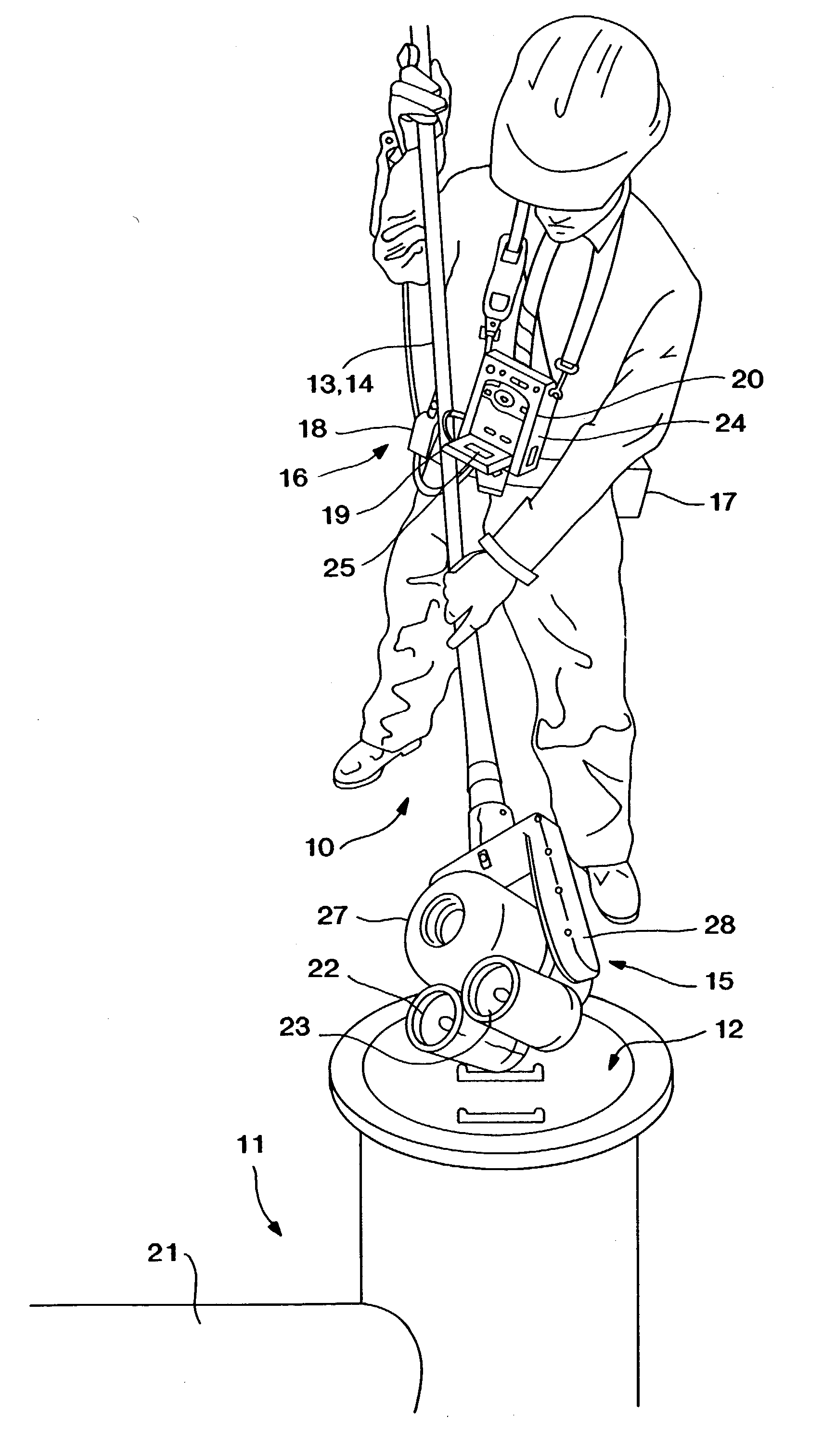
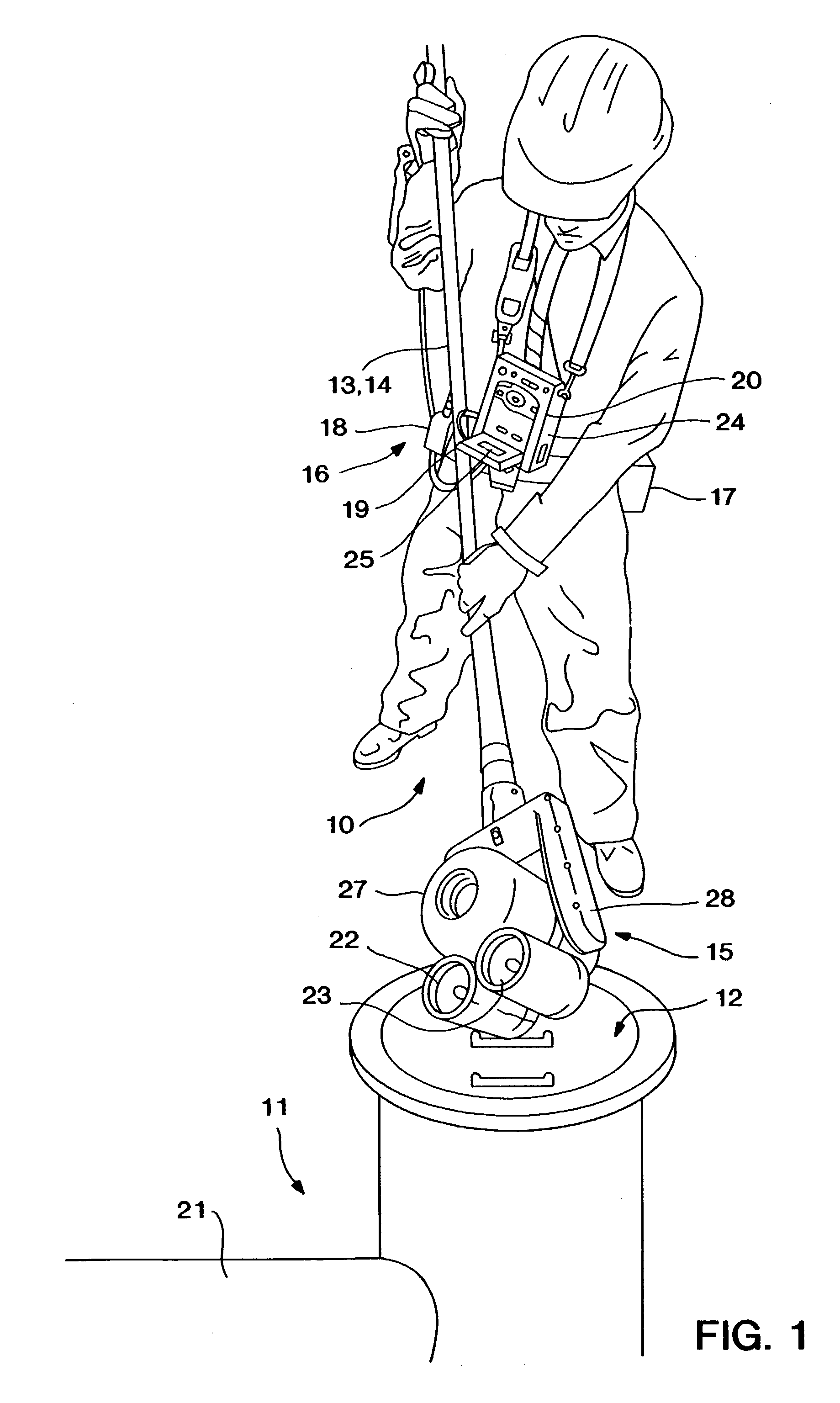
[0028] Referring to the drawings, FIG. 1 shows a user using a preferred embodiment of the inspection system 10 to ascertain whether an invasive procedure is warranted. Using the system comprises the steps of (a) positioning an imaging system 15 independently of a support system 16 such that a target area is in the field of view while at a first magnification level; (b) imaging a target area at a second magnification level greater than the first magnification level; (c) outputting an image of the target area; (d) evaluating the image to determine whether the target area is acceptable or whether an invasive procedure is warranted, and (e) performing the invasive procedure if necessary. Each of these steps is considered in greater detail below. It should be understood, however, that the classification of the process in these discrete steps is for illustrative purposes and should not be construed to limit the scope of the invention. For example, it is anticipated that two or more steps ...


PUM

PropertyMeasurementUnit
focal lengthaaaaaaaaaa
areaaaaaaaaaaa

Abstract

A process for maintaining an area using a non-invasive inspection device, the inspection device comprising at least: an imaging system having an adjustable field of view and an imaging device for transmitting an electrical signal corresponding to an area within the field of view; a portable support system operatively connected to the imaging system and adapted to provide functional support to the imaging system; and a positioning system connected to the imaging system and adapted for moving the imaging system independently of the portable support system; the process comprising: (a) positioning the imaging system independently of the support system such that a target area is in the field of view while at a first magnification level; (b) imaging a the target area at a second magnification level greater than the first magnification level; (c) outputting an image of the target area; (d) evaluating the image to determine whether the target area is acceptable or whether an invasive procedure needs to be performed; and (e) performing the invasive procedure on the target area if needed.

Description

REFERENCE TO RELATED APPLICATIONS[0001] This application claims priority to provisional application No. 60 / 132,400, filed May 4, 1999, and U.S. application Ser. No. 09 / 564,953, filed on May 4, 2000. Both of these applications are hereby incorporated by reference.[0002] The present invention relates generally to the inspection of areas which are hard-to-read, inaccessible or uninhabitable for humans. More specifically, the invention relates to the inspection of manholes and the lateral pipes radiating therefrom prior to invasive procedures such as cleaning and comprehensive exploratory inspections.[0003] It is often necessary to inspect and maintain areas under conditions which render them inaccessible or otherwise uninhabitable by humans for an extended period. These conditions include, for example, small confined spaces and harsh environments such as insufficient air / oxygen, presence of toxins, radioactivity, contamination, excessive dust, dirt and filth, and high noise levels. The...

Claims


Application Information

Patent Timeline
Patent Type & Authority Applications(United States)
IPC IPC(8): E03F7/12G01N21/954H04N7/18
CPCE03F7/12H04N7/183G01N21/954
Inventor DROST, JEFFREY D.PELLEGRINO, BRUCE A.
Owner ENVIROSIGHT
Why Eureka
Try Eureka