Mortise lockset with internal clutch having override feature

a technology of override feature and lockset, which is applied in the direction of keyhole guards, mechanical control devices, instruments, etc., can solve the problems of assembly inoperative, mechanism jamming and becoming inoperable, and vulnerable locking mechanism, so as to prevent the locking piece from jamming

Inactive Publication Date: 2003-04-08
HARROW PRODS
View PDF21 Cites 53 Cited by
  • Summary
  • Abstract
  • Description
  • Claims
  • Application Information

AI Technical Summary

Benefits of technology

Briefly stated, the invention in a preferred form is a lockset which includes a housing and a latch extending from the housing. The latch has an extended position and a retracted position. The mechanism includes apparatus for biasing the latch to the extended position, apparatus for defining a locked mode and an unlocked mode, and apparatus for transferring an operator input motion to move the latch to the retracted position in the unlocked mode. The apparatus for transferring includes a locking piece, a cam surface and a cam follower. A spring biases the cam follower in a first direction toward the cam surface and a second spring provides an override movement of the locking piece to thereby compensate for any off-center relationship between the rotation axis of the follower and the cam surface and to prevent jamming of the locking piece.
An object of the invention is to provide a lock mechanism that will minimize the risk of jamming of the mechanism despite repeated use of the mechanism for a very large number of duty cycles.
Another object of the invention is to provide a lock mechanism that will function consistently to self compensate for liberal manufacturing tolerances, assembly misalignment, wear and / or extreme forces applied to the mechanism.

Problems solved by technology

In some cases known clutch mechanisms have been vulnerable, particularly after years of service, due to wearing of the individual parts thereof.
This may lead to mechanisms that jam and become inoperative.
In some cases, however, wear of the components may result in malfunctions such as jamming or make the assembly inoperative and prevent access to the secured side of the door or even prevent egress from the secured side to the unsecured side.

Method used


Image

  • Mortise lockset with internal clutch having override feature
  • Mortise lockset with internal clutch having override feature
  • Mortise lockset with internal clutch having override feature

Examples


Embodiment Construction

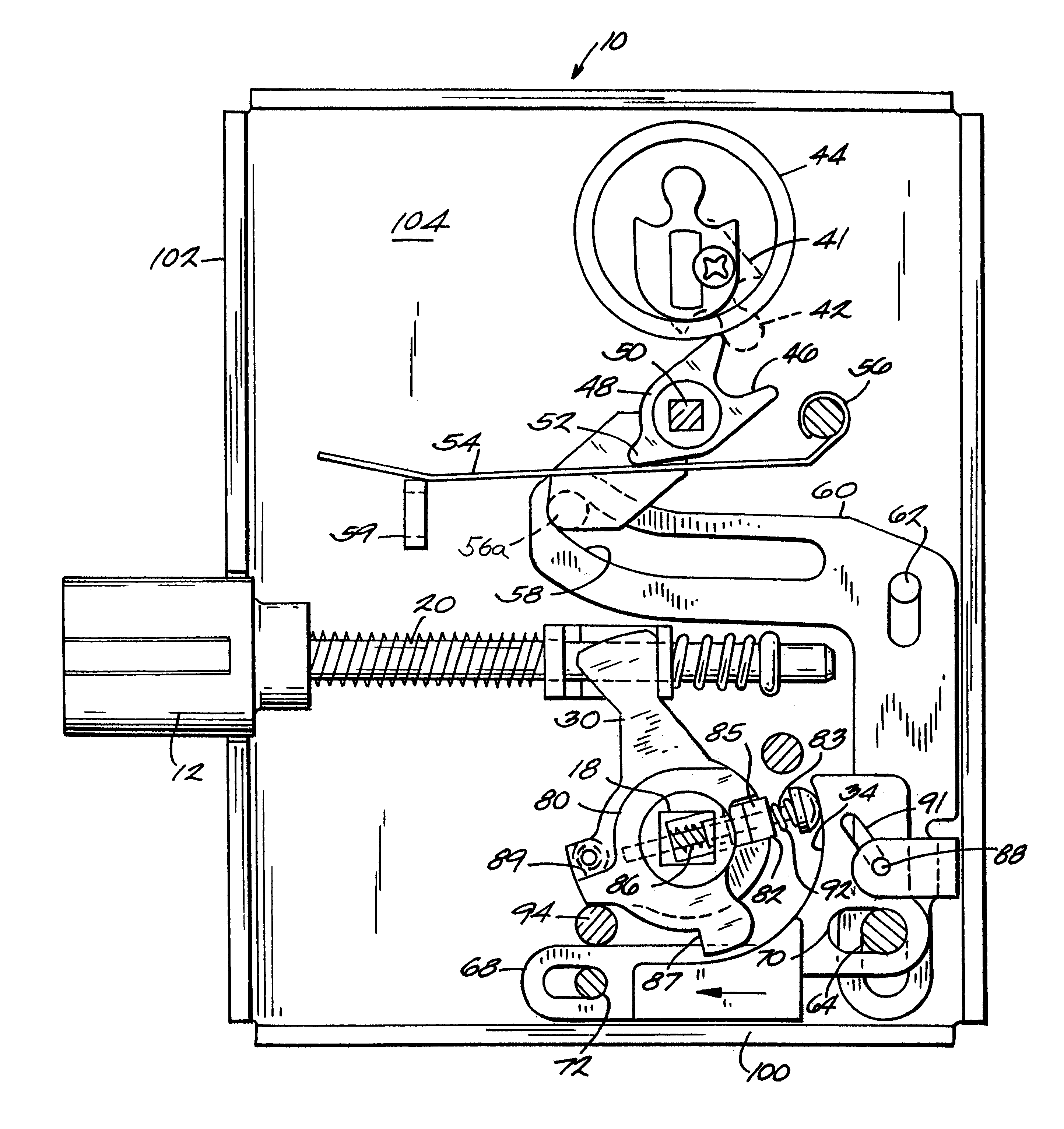
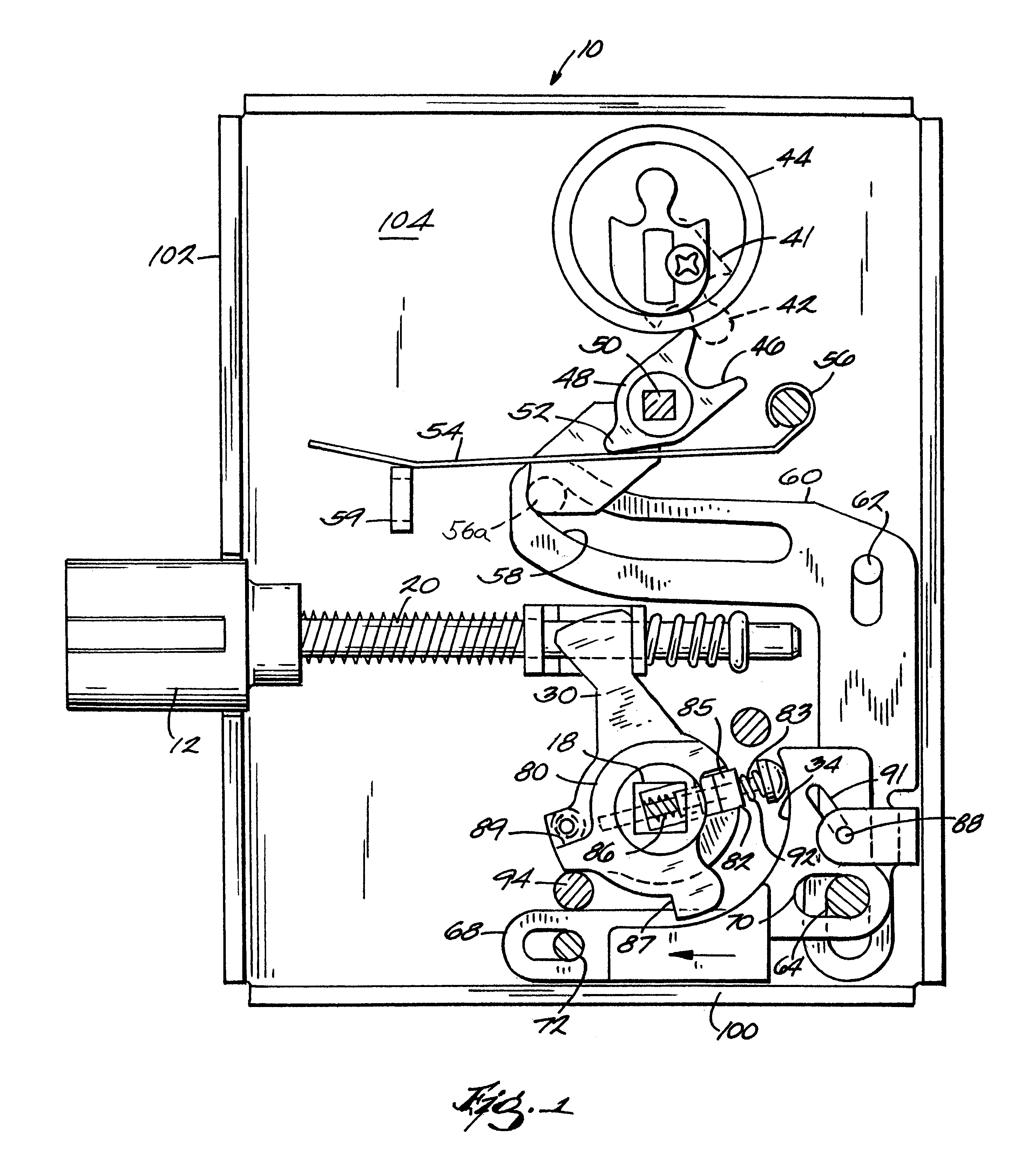
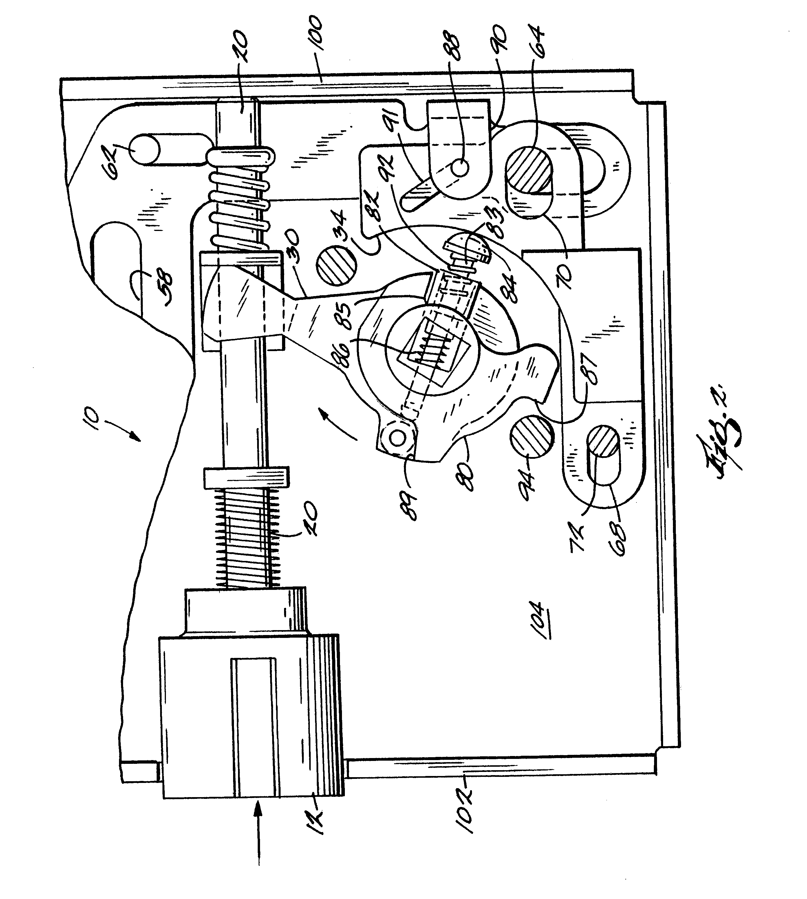
With reference to the drawings wherein like numerals represent like parts throughout the several figures, one embodiment of the mortise lockset, in accordance with the present invention is generally designated by the numeral 10. The mortise lockset 10 is mountable in the mortise of a door (not illustrated) and is adapted to engage the strike of a doorframe (not illustrated). The mortise lockset 10 is equipped with both key and thumb turn locking assemblies disposed, respectively, on the outside (unsecured side) and the inside of the enclosure, such as a room, being secured by the lock mechanism. It will be understood that for the illustrated environment, the lockset is always unlocked from the secured side because it is located at the interior of the secured enclosure and is used only for egress from the enclosure.

The mortise lockset 10 comprises a substantially rectangular lock case 100 that includes an integral backing plate 104. The case 100 provides a mounting surface for the co...


PUM


Abstract

A lock mechanism has a housing and a latch extending from the housing. The latch has an extended position and a retracted position. The mechanism includes apparatus for biasing the latch to the extended position, apparatus for defining a locked mode and an unlocked mode, and apparatus including a clutch for transferring an operator input motion to move the latch to the retracted position in the unlocked mode. The clutch includes a cam surface and a cam follower. A spring biases the cam follower toward the cam surface and a second override spring which biases the cam follower to compensate for any off-center relationship due to wear, excessive force and / or assembly misalignment and to prevent jamming.

Description

BACKGROUND OF THE INVENTION1. Field of the InventionThis invention relates generally to mechanical locksets employed to secure doors. More particularly, the present invention relates generally to a mortise-type lockset that incorporates an internal clutch assembly.2. Description of the Related ArtRecent hardware trends and the Americans with Disabilities Act requirements for lever handles at both exterior and interior sides of doors have focused the market on lever operated lock mechanisms. Because both intruders and users can impose greater forces on the lock mechanism having lever operating systems, it is particularly important to provide a mechanism that is not vulnerable to being compromised intentionally or otherwise. In some cases lever operated lock mechanisms have included a mechanical clutch mounted between the operator or operating handle and the lockset. Such clutches selectively mechanically couple the operating handle to the lockset and permit rotation of the operating ...

Claims


Application Information

Patent Timeline
Patent Type & Authority Patents(United States)
IPC IPC(8): E05B13/00E05B63/00E05B47/06E05B25/00
CPCE05B13/005E05B47/0688E05B63/0069Y10T70/5496Y10T70/5805Y10T70/5221Y10T70/5823
Inventor FROLOV, GEORGE
Owner HARROW PRODS
Why Eureka
Try Eureka