Self-oscillation type switching power supply unit
a power supply unit and self-oscillation technology, applied in pulse generators, pulse techniques, instruments, etc., can solve the problems of increased input power and heat-production problems of switching transistors, loss at light loading cannot be improved, and the problem of switching power supply units with problems
- Summary
- Abstract
- Description
- Claims
- Application Information
AI Technical Summary
Problems solved by technology
Method used
Image

Examples
first embodiment
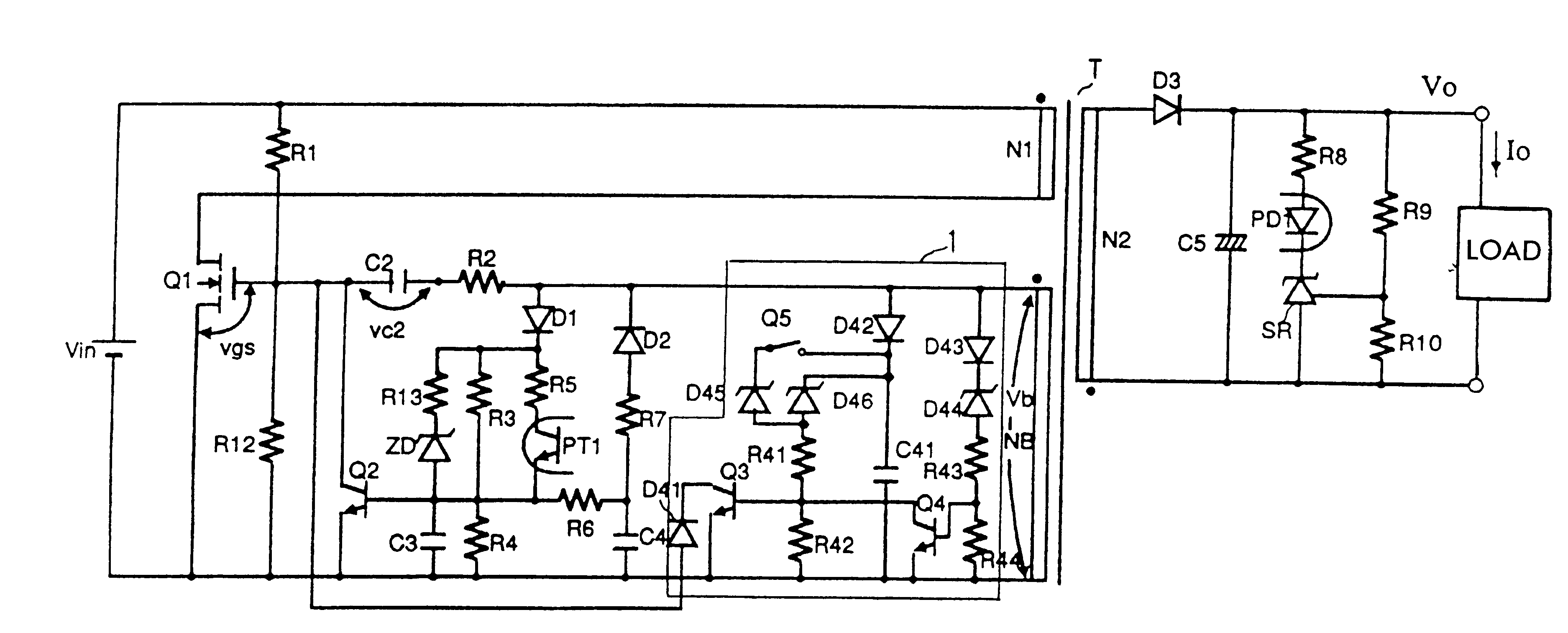
FIG. 5 is a circuit diagram of a self-oscillation type switching power supply unit according to the present invention.
A switching transistor Q1, e.g., a MOS-FET, is connected in series to a primary winding N1 of a transformer T, and a feedback winding NB of the transformer T constitutes a feedback circuit to the switching transistor Q1. A rectifying and smoothing circuit comprising a rectifying diode D3 and a smoothing capacitor C5 is provided in a secondary winding N2 of the transformer T. Furthermore, in the output portion of the rectifying and smoothing circuit, a voltage divider circuit of resistors R9 and R10 and a voltage detector circuit comprising a shunt regulator SR, a light-emitting element PD1 of a first photo coupler, and a resistor R8 are provided.
The difference between the circuit of the present embodiment shown in FIG. 5 and the conventional circuit shown in FIG. 1 is that an oscillation frequency control circuit 1 is provided in the circuit in FIG. 5.
In the oscillat...
third embodiment
FIG. 9 is a circuit diagram of a self-oscillation type switching power supply unit according to the present invention.
The self-oscillation type switching power supply unit is different from the self-oscillation type switching power supply unit shown in FIG. 8 in that the switch Q5 in FIG. 8 is replaced with a phototransistor PT2 of a photocoupler and that the light-emitting photodiode PD2 of the photocoupler is connected to an external remote signal input terminal REM.
In such a construction, the phototransistor PT2 can be turned on by only inputting a remote signal into the remote signal input terminal REM. Accordingly, when constructed such that a HIGH signal is input to the remote signal input terminal REM in the normal operation mode and the standby mode and a LOW signal is input to the remote signal input terminal REM in the wait mode, it is easy to set the operation mode.
fourth embodiment
FIG. 10 shows a circuit diagram of a self-oscillation type switching power supply unit according to the present invention.
The self-oscillation type switching power supply unit is different from the self-oscillation type switching power supply unit shown in FIG. 9 in that a resistor R50 for detecting light or heavy loading and a switching circuit 3 for controlling the turn-on and turn-off of the phototransistor PT2 based on the voltage across the resistor R50 are provided.
Two comparators COMP-1 and COMP-2 are provided in the switching circuit 3. The comparator COMP-1 detects the voltage across the resistor R50 and the rated load or light loading. In the case of the rated load, since the voltage across the resistor R50 is large, the output of the comparator COMP-1 is grounded. Furthermore, in the case of light loading, the output of the comparator COMP-1 is made open. The comparator COMP-2 compares the reference voltage Vref and the charged voltage of the capacitor C11, and turns off ...
PUM
 Abstract
Description
Claims
Application Information
 - R&D
- Intellectual Property
- Life Sciences
- Materials
- Tech Scout
- Unparalleled Data Quality
- Higher Quality Content
- 60% Fewer Hallucinations
Browse by: Latest US Patents, China's latest patents, Technical Efficacy Thesaurus, Application Domain, Technology Topic, Popular Technical Reports.
© 2025 PatSnap. All rights reserved.Legal|Privacy policy|Modern Slavery Act Transparency Statement|Sitemap|About US| Contact US: help@patsnap.com