Interior space-dividing wall system

a technology of interior space and wall panels, which is applied in the field of space-dividing wall panels, can solve the problems of limited cabling capacity, difficult to accommodate all of the power and telecommunication cabling for all workstations associated with a particular group of workstations, and difficult to reconfigure workstations

Inactive Publication Date: 2003-05-06
HAWORTH SPA
View PDF31 Cites 74 Cited by
  • Summary
  • Abstract
  • Description
  • Claims
  • Application Information

AI Technical Summary

Problems solved by technology

In such an arrangement, however, the wall panels typically have a relatively narrow thickness to minimize the floor space being used and thereby have a limited cabling capacity.
As a result, it may become difficult to accommodate all of the power and telecommunication cabling for all of the workstations associated with a particular group of workstations.
This arrangement, however, requires the removal of furniture components when moving these components between panels and also routes horizontal cabling through the posts which thereby makes reconfiguration of workstations more difficult.
Constructing the spine wall using the box-beam, however, does restrict interior usage of the panel.
While the known "spine" wall systems generally all function in a generally satisfactory manner, nevertheless most such systems possess structural, appearance, assembly or operational features which are believed to be less than optimal.
More specifically, some of the more commonly experienced disadvantages with various known wall systems are: an inability to mount external loads and specifically branch panels in an off-modular relation or, while some known systems permit off-module mounting, nevertheless many permit off-module mounting only in a restricted manner in that off-module mounting can occur only at selected locations, and as such the system still possesses so-called "dead zones" which are locations where significant off-module external loading is not permittted; some known systems do not provide optimum flexibility with respect to maximizing the types of tiles or pads which mount on the wall panels, particularly with respect to maximization of pad flexibility both vertically and horizontally so as to provide a wide variety of different appearance and use characteristics in the adjacent workstations; many of the systems require use of branch or divider panels which are constructed like the spine panels and hence such branch panels are oftentimes over-designed for their intended use and hence result in the overall system being of significantly increased cost; many known systems provide panels which extend vertically so as to substantially contact the floor along the complete lower edge thereof and hence undesirably impede or restrict proper air circulation in the adjacent workstations; many such systems do not efficiently permit cabling (electrical and / or telecommunication) to be readily fed into the interior of the wall panels from an exterior source, particularly from cabling disposed below a raised floor, without use of unsightly external connectors.

Method used


Image

  • Interior space-dividing wall system
  • Interior space-dividing wall system
  • Interior space-dividing wall system

Examples


Embodiment Construction

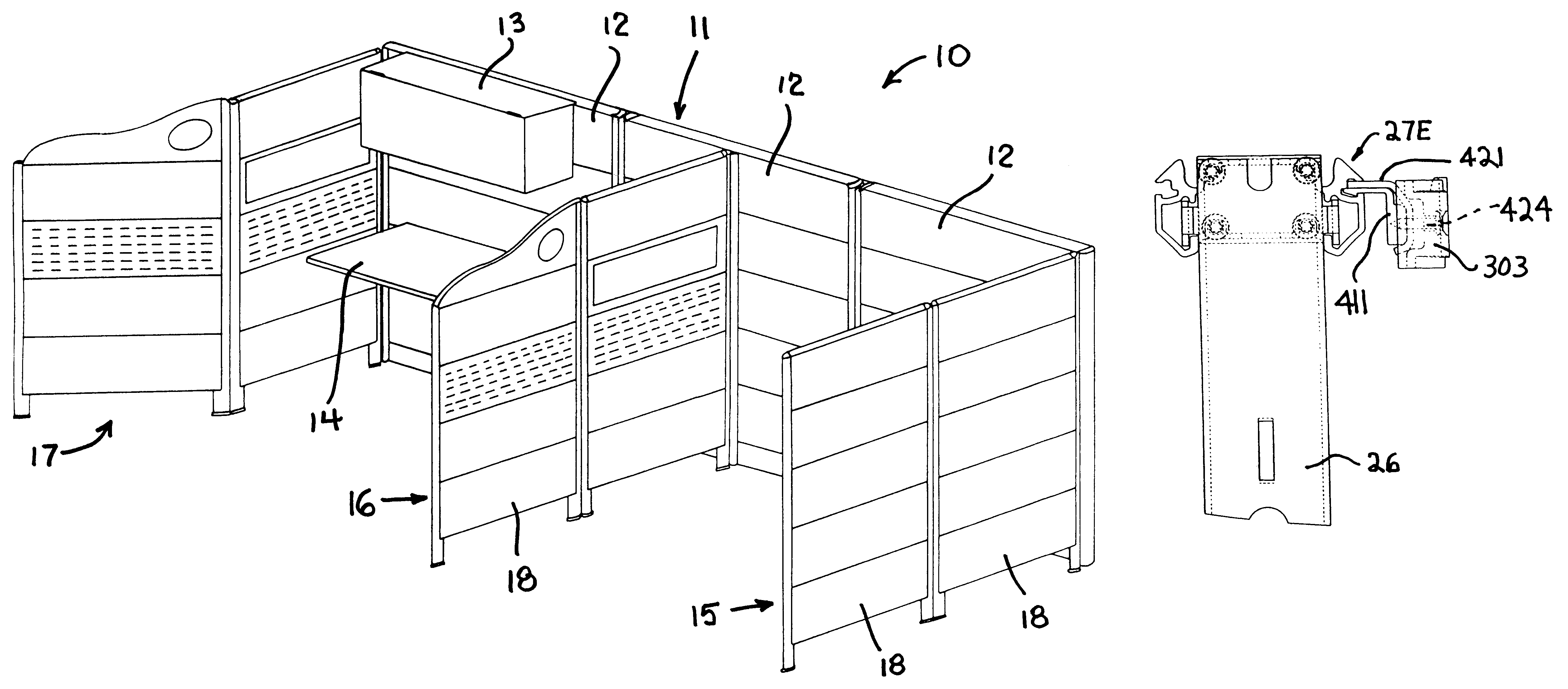
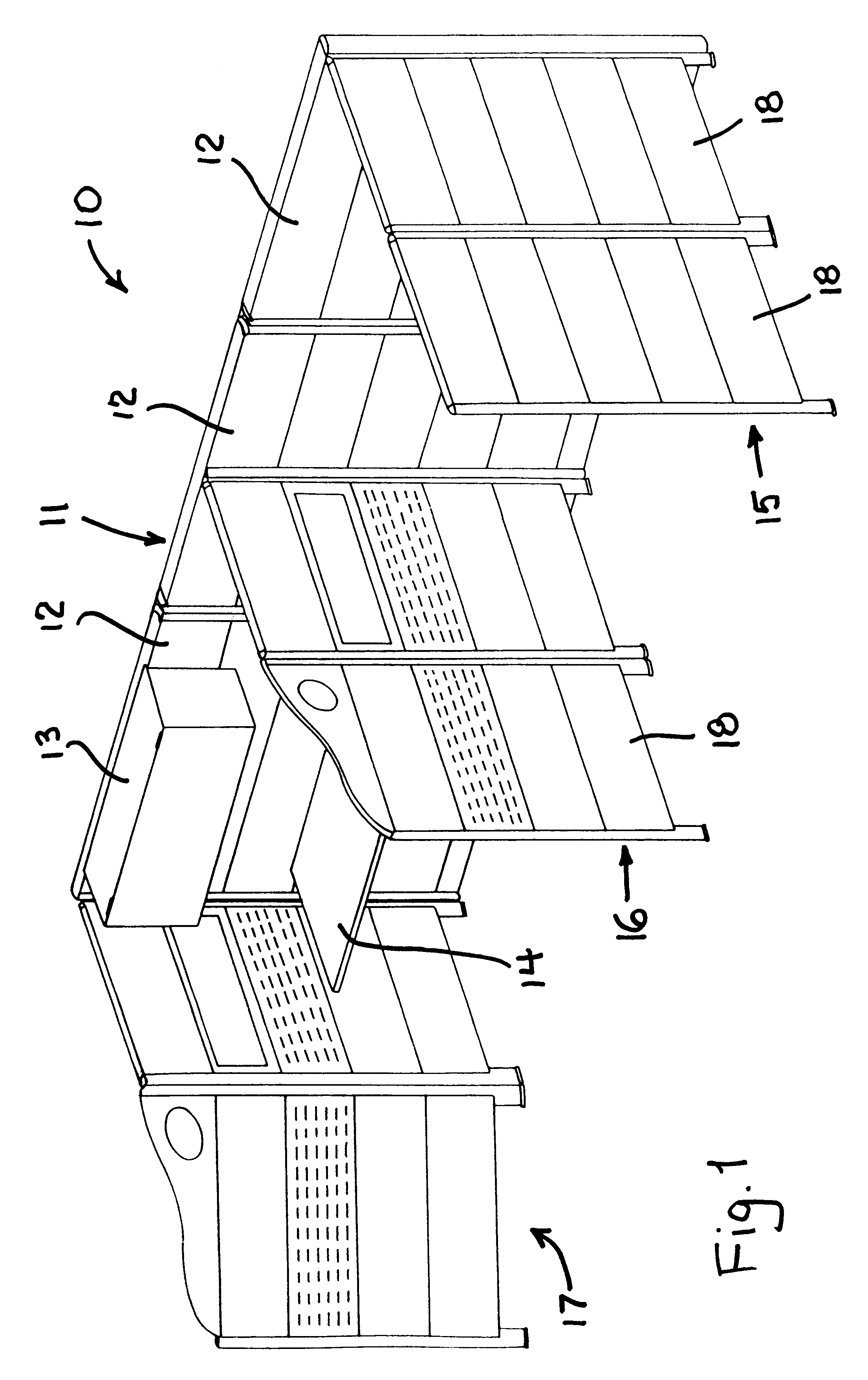
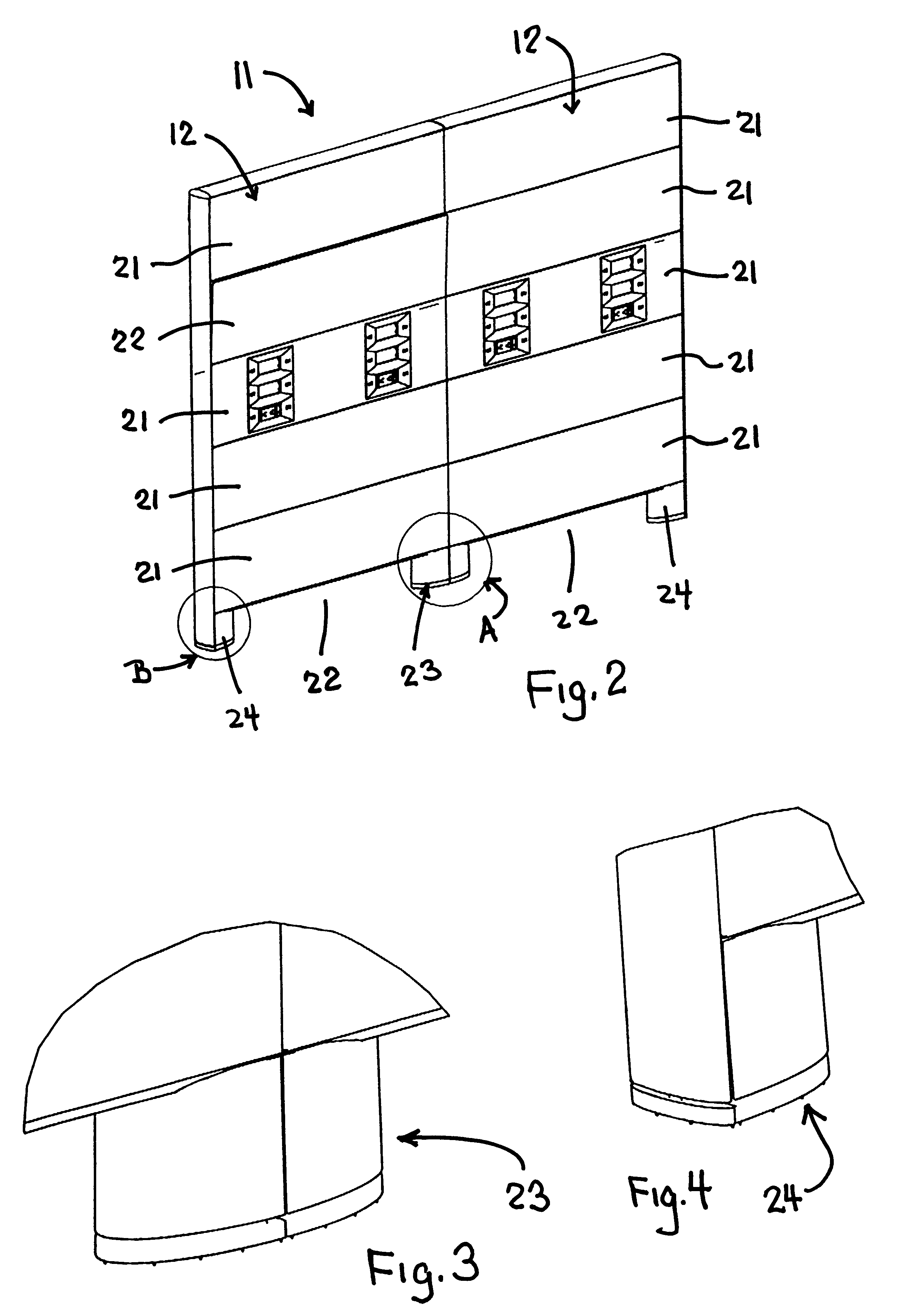
Referring to FIG. 1, there is illustrated an interior, space-dividing upright wall system 10 which can be disposed for free-standing support on a floor so as to divide a large open area into smaller work spaces. The wall system 10 includes an upright main or spine wall 11 which is defined by a plurality of upright main or spine panels 12 (three panels in the illustrated arrangement). The spine wall 11 is adapted to support external load components thereon, such as illustrated by a wall cabinet 13 and a worksurface 14 which are mounted in cantilevered relationship on one side of the main wall.

The wall system 10 in the illustrated arrangement also includes a plurality of divider walls 15, 16 and 17 which cooperate with and, in the illustrated arrangement, connect to the main wall 11 and project transversely therefrom so as to effect separation between individual work spaces. The divider walls in the illustrated arrangement are defined by one or more upright branch panels 18 serially c...


PUM


Abstract

A wall system and particularly a load-bearing spine wall defined by rigidly connected spine panels which are usable in conjunction with and connectable to branch panels for defining workstations. These spine panels include an interior frame having plural hollow cross beams rigidly joined between parallel uprights. The cross beams have elongate slots extending lengthwise along the sidewalls thereof. Each side of the frame permits one or more removable covering tiles to be attached thereto for defining the exterior surface of the spine panel. Load-bearing components having cantilevered hangers can be engaged within the elongate slots which extend lengthwise of the cross beams. Vertically adjacent tiles have longitudinal edges spaced to define a narrow elongate passage therebetween which aligns with the mouth of a respectively adjacent hanger-accommodating slot.

Description

FIELD OF THE INVENTIONThis invention relates to a space-dividing wall panel system formed from upright panels for use in dividing large open office areas into smaller work spaces and, more specifically, to a wall panel system defining an improved load-bearing and cable-accommodating main or "spine" wall to which return or branch walls are connectable to define individual workstations.This invention also relates to an improved load-bearing main or spine panel which cooperates with similar such panels to define a spine wall, and further relates to an improved branch panel which is connectable in an off-modular manner to the main wall.BACKGROUND OF THE INVENTIONCommercial buildings typically include large open office areas which are divided into smaller work spaces or workstations by any of a number of space divider and panel systems that have been developed therefor. These space divider arrangements typically employ upright space-dividing wall panels which serially connect together to...

Claims


Application Information

Patent Timeline
Patent Type & Authority Patents(United States)
IPC IPC(8): A47B83/00E04B2/74E04B2/82
CPCA47B83/001E04B2/7425E04B2/7427E04B2002/742E04B2002/749E04B2002/7468E04B2002/7483E04B2002/7487E04B2002/7488E04B2002/7464
Inventor MARSHALL, DALE R.LONG, DARREN R.VALLAS, RODNEYGOODCHILD, JIM THOMPSONSTEEVES, ROBERT E.
Owner HAWORTH SPA
Why Eureka
Try Eureka