Unit and method for bending wood

a technology of bending wood and unit, applied in the field of unit and a method for bending wood, can solve the problems of difficult to bend or shape wood, difficult to bend strong wood, difficult to operate, etc., and achieve the effect of easy and quick set up, and quick and easy movement and adjustment of blocks

Inactive Publication Date: 2003-06-03
PATTON ARLISS
View PDF10 Cites 9 Cited by
  • Summary
  • Abstract
  • Description
  • Claims
  • Application Information

AI Technical Summary

Benefits of technology

Using the machine and method of the present invention permits wood, even laminated wood, to be bent in a very accurate manner, while still being easily and quickly set up and carried out even by a relatively unskilled worker. The continuous and uninterrupted nature of the control curve permits the form blocks and the clamp blocks to be set at any and all desired locations whereby the most effective application of bending forces can be applied to the wood. The holding and clamp blocks apply even pressure to the wood over the entire width of the wood, no matter how wide or narrow the wood, whereby no slippage between laminated layers will occur during the bending and drying process. Due to the continuous and uninterrupted nature of the control curve, the form and clamp blocks can be easily and quickly set up even by a non-skilled worker so the machine and process of the present invention are extremely versatile. The electromagnetic features of the machine and process permit quick set up of the machine and its parts, yet will hold the form and clamp blocks securely enough even for thick wood. The form and clamp blocks can be easily moved into the desired locations and then the electromagnets activated to securely fix those elements in place. Since the electromagnets are not activated until after the blocks are in the desired locations, movement and adjustment of the blocks is quick and easy. Since the blocks are held electromagnetically, the blocks are held in place securely enough for all purposes and applications.
The machine and process are extremely versatile so the workpiece-supporting surface can be used for other jobs as well as simply bending wood. Still further versatility is added because the machine and process of the present invention is amenable to use with conventional techniques and knowledge so a worker is not required to learn new techniques which will substantially increase the efficiency of the machine and process. Many different types of curves, even complex and compound curves, are easily formed using the machine and process of the present invention. The workpiece-supporting surface can be easily fit into any available space

Problems solved by technology

However, strong wood may be difficult to bend because the very characteristic desired, strength, makes it difficult to bend or shape the wood.
While somewhat successful in some applications, these machines can be very complex, expensive and difficult to operate.
Often, such machines require special skills of an operator thereby limiting the versatility of such machines.
If a worker must learn special techniques to operate a machine, there will be a loss of time during the learning process.
There may even be a loss of product as mistakes are made during the learning process.
However, during the drying process for the adhesive, the individual layers can slip relative to each other.
Such a situation is very undesirable as the finished product may be unusable.
Many machines and processes for bending wood have a disadvantage if laminated products are to be bent because the layers may slip relative to each other during the bending process.
This may be especially true if the laminated product is difficult to bend and requires great pressure to achieve the desired bending.
Great bending pressure may increase the possibility of layer relative slippage in a laminated product.
While the art has many machines that can bend wood, some of these machines are so complicated to set up and operate that only highly skilled and specialized workers can properly operate them.
Thus, only workers who are adept at computer programs can fully obtain the benefits of such machines.
While the above-discussed drawbacks inhibit the full realization of the advantages associated with woodbending, by far the most serious disadvantage of presently-available machines and processes is the limited nature of the control that can be exercised over the curve being set for the wood.
That is, some parts of the desired curve cannot be fully controlled using presently-available machines and processes.
There are discontinuities in the control curve of presently-available machines and processes.
Such discontinuities are inherent in a digital control and cannot be avoided.
Thus, there will be some areas of a digitally set control curve that simply cannot be controlled due to the inherent discontinuous nature of digital control.
Still further, many woodworking processes generate a great deal of debris, such as dust, adhesive and the like.
Such debris may clog or damage presently-available machines, especially those that have a great many complicated and complex parts, such as screws, computers and the like.
Such machines may have to be cleaned on a very short interval.
This may be costly in time as well as manpower.
Still further, many presently-available machines are difficult to clean.
Thus, if adhesive or dust settles in the parts of some presently-available machines, the machine may be subject to a long downtime and may require a great deal of service to clean.
This can be expensive in both time and costs and thus can be undesirable.
Most presently-available machines are quite bulky and large.
Therefore, when the machine is not in use, a great deal of space can be occupied that might otherwise be used for other purposes.
This can translate into a cost.
Such machines may not be easily adapted for other applications and thus are not as versatile as they could be.
Such lack of versatility can be viewed as an increase in cost for the machine.
Many presently-available machines and processes require complex procedures for set up.
Such machines cannot be quickly set up especially by an unskilled worker.
Long set up times can be costly.

Method used


Image

  • Unit and method for bending wood
  • Unit and method for bending wood
  • Unit and method for bending wood

Examples


Embodiment Construction

Other objects, features and advantages of the invention will become apparent from a consideration of the following detailed description and the accompanying drawings.

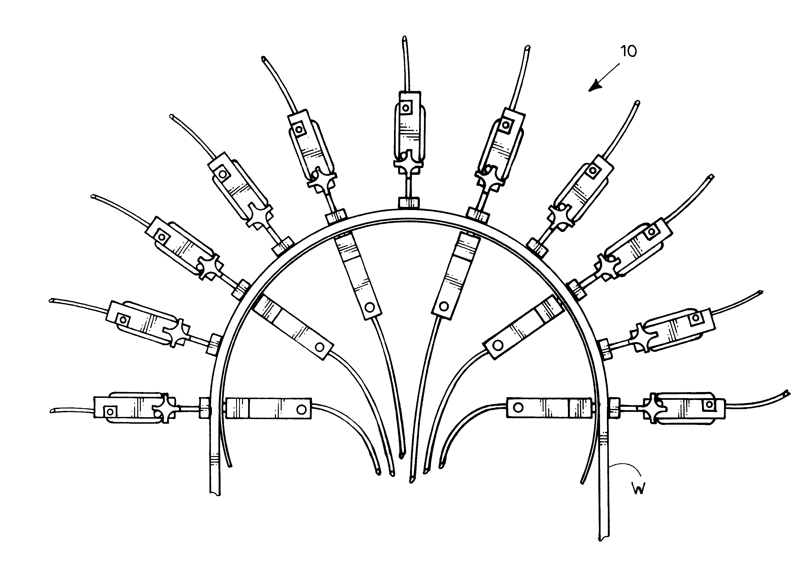
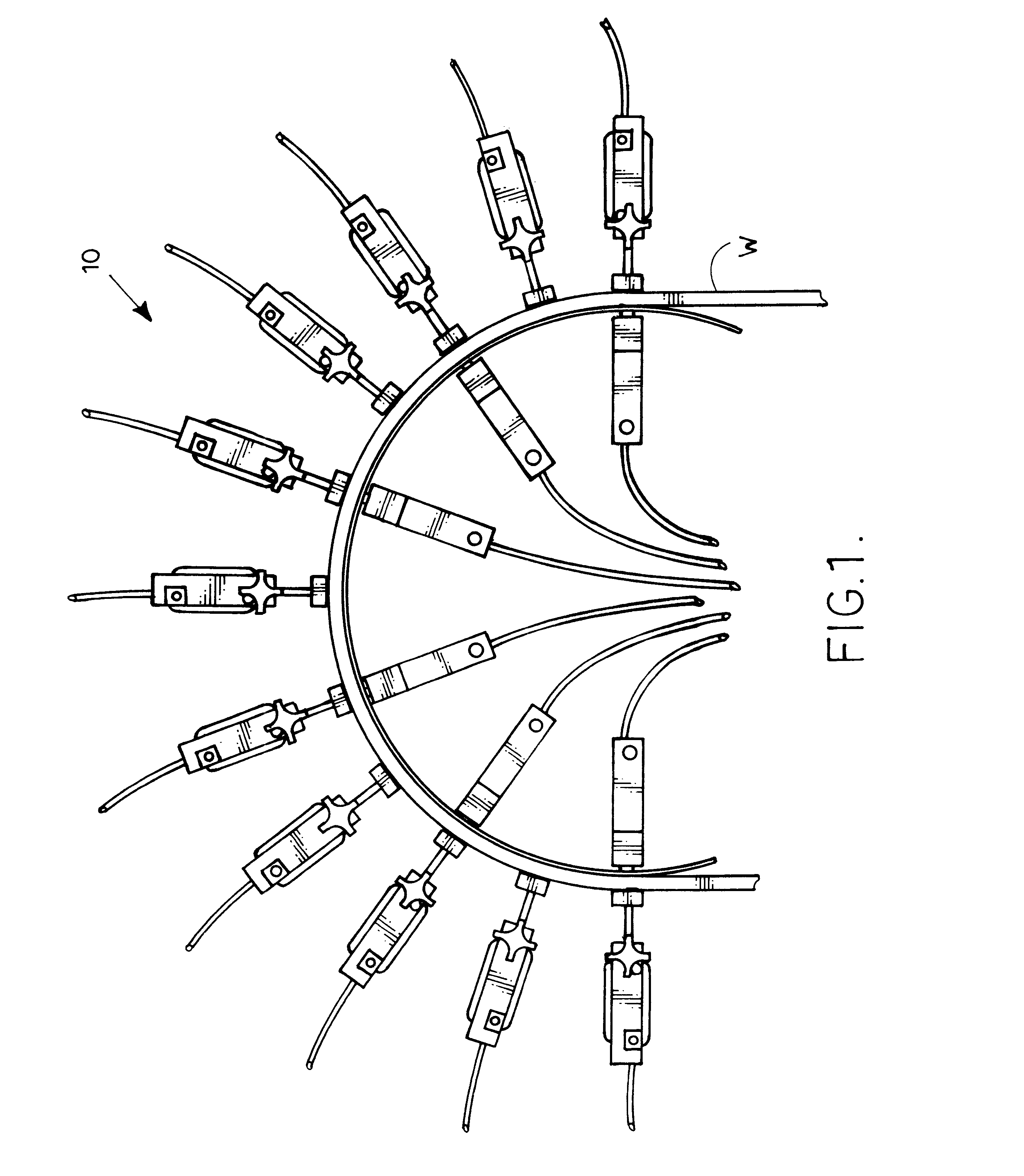
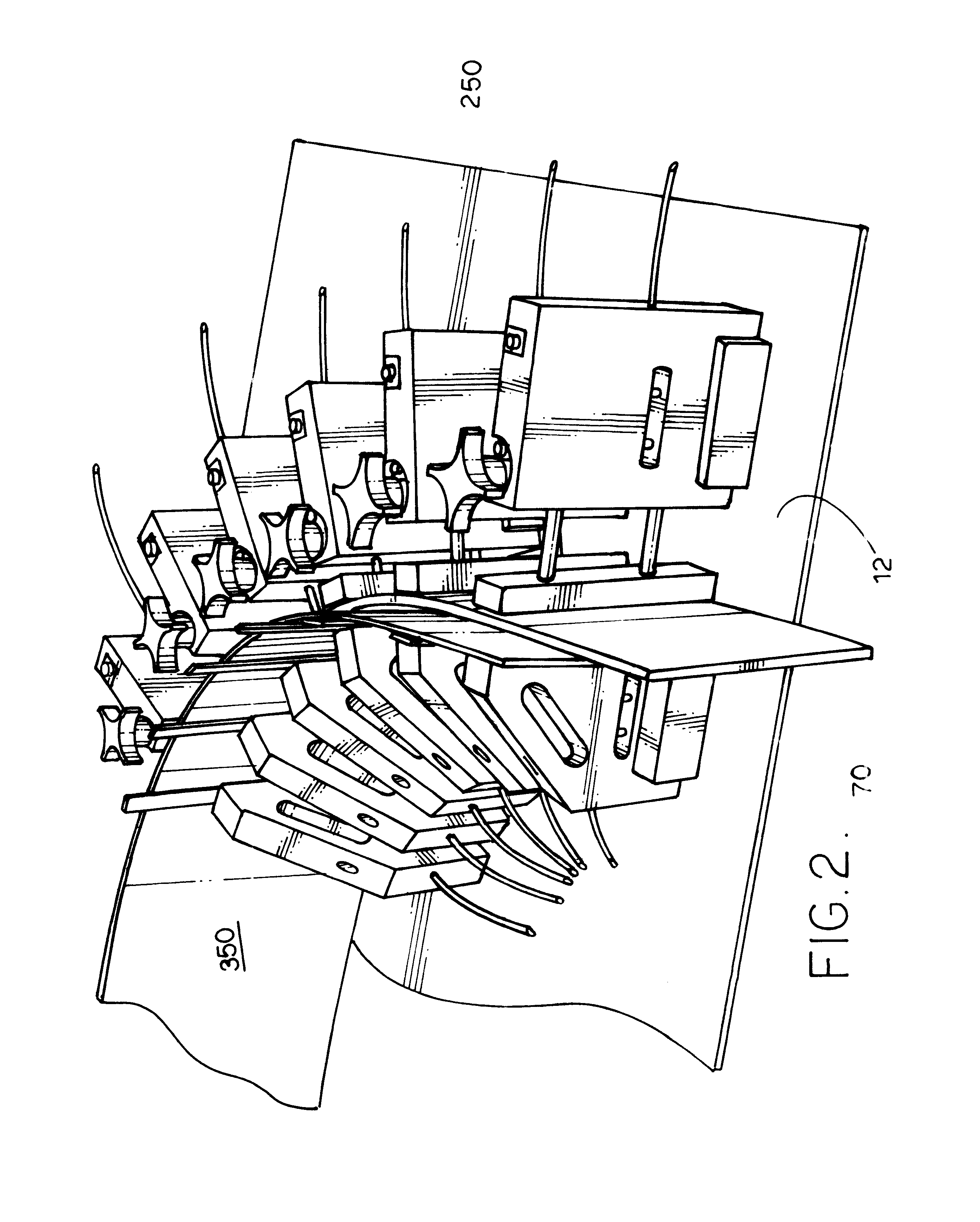
The machine and method embodying the teaching of the present invention quickly and easily defines a continuous and uninterrupted control curve and then permits quick and easy set up of wood contacting elements along that control curve whereby any desired degree of accuracy can be easily achieved even by a non-skilled worker. Compound and complex wood curves can be easily achieved, and the equipment is not subject to damage by debris and can be easily cleaned if debris is present. The wood contacting elements are held in place by electromagnets so they are easily and quickly moved into desired positions, and then can be quickly activated to be securely held in place even if the wood being bent is thick and difficult to bend.

Referring to the figures, the machine or unit embodying the present invention will be described fi...


PUM

PropertyMeasurementUnit
shapesaaaaaaaaaa
widthaaaaaaaaaa
lengthaaaaaaaaaa

Abstract

Wood is bent using a unit and a method in which a continuous and uninterrupted curved path is defined over a workpiece-supporting surface and form and clamp blocks are electromagnetically attached to the workpiece-supporting surface adjacent to the path. The form and clamp blocks engage a wood workpiece to force that workpiece into a shape that matches the path defined over the workpiece-supporting surface.

Description

The present invention relates to the general art of woodworking, and to the particular field of woodworking with bending, and specifically to woodworking with bending concurrent with or subsequent to bonding.The building industry has long used wood that has been shaped into arcuate shapes. Such arcuate shapes have been used in doorways, windows and the like as well as many other applications that will occur to those skilled in the art. Some of the shapes require simple curves, while others may require complex and / or compound curves. These curved shapes have been achieved using wood that has been specially grown, or combining short wood shapes, or by bending wood into the desired shape. Bending wood provides the most versatility and thus is the most desirable for modern needs.Some applications require strong wood, as for supports or the like. However, strong wood may be difficult to bend because the very characteristic desired, strength, makes it difficult to bend or shape the wood. ...

Claims


Application Information

Patent Timeline
Patent Type & Authority Patents(United States)
IPC IPC(8): B25B11/00B25B1/06B25B1/00B25B5/06B25B5/00B27H1/00B27M3/00
CPCB25B1/06B25B5/003B25B5/06B25B11/002B27M3/0053B27H1/00Y10T29/49627Y10S269/91Y10S100/917Y10T29/49895
Inventor PATTON, ARLISS
Owner PATTON ARLISS
Why Eureka
Try Eureka