Adjustable musician's stand

a technology for musicians and stands, applied in the direction of furniture parts, instruments, music aids, etc., can solve the problem of insufficient space to set up all of their electronic equipment in a reasonably effective manner, and achieve the effect of efficient use of available floor space, simple and quick folding or compacting

Inactive Publication Date: 2009-04-07
BRUCE HARPER M
View PDF4 Cites 18 Cited by
  • Summary
  • Abstract
  • Description
  • Claims
  • Application Information

AI Technical Summary

Benefits of technology

[0017]A stand for use as a microphone stand, music stand, or instrument stand is provided having a telescopingly adjustable base arrangement which is designed to be used particularly in relatively cramped stage or performing areas where there is a need to conserve space, although such arrangement could be used in any performing area. Performers, particularly those musicians or bands performing in a small club or bar environment, often encounter a problem in that there is insufficient room to set up all of their electronic equipment in a reasonably effective manner. The present invention addresses this problem by providing a stand having a generally U-shaped frame or support providing floor space within the center of the “U” and wherein the length of the support members is adjustable so that the support members can be positioned compactly around other equipment such as processors or controllers, thereby more efficiently using the available floor space in setting up such equipment. The pitch or angle of the vertical microphone support column can be adjusted using screw-type foot members on the bottom of the stand. In addition, the foot members provide sufficient room between the floor and horizontal support members so that electric control wires powering the effects processor, instruments, or other equipment can be slipped under such members. The stand as well as the instrument and equipment support features also may be simply and quickly folded or compacted into an easy to carry package for transportation and storage purposes.

Problems solved by technology

Performers, particularly those musicians or bands performing in a small club or bar environment, often encounter a problem in that there is insufficient room to set up all of their electronic equipment in a reasonably effective manner.

Method used


Image

  • Adjustable musician's stand
  • Adjustable musician's stand
  • Adjustable musician's stand

Examples


Embodiment Construction

[0073]The following detailed description is of the best mode or modes of the invention presently contemplated. Such description is not intended to be understood in a limiting sense, but to be an example of the invention presented solely for illustration thereof, and by reference to which in connection with the following description and the accompanying drawings one skilled in the art may be advised of the advantages and construction of the invention.

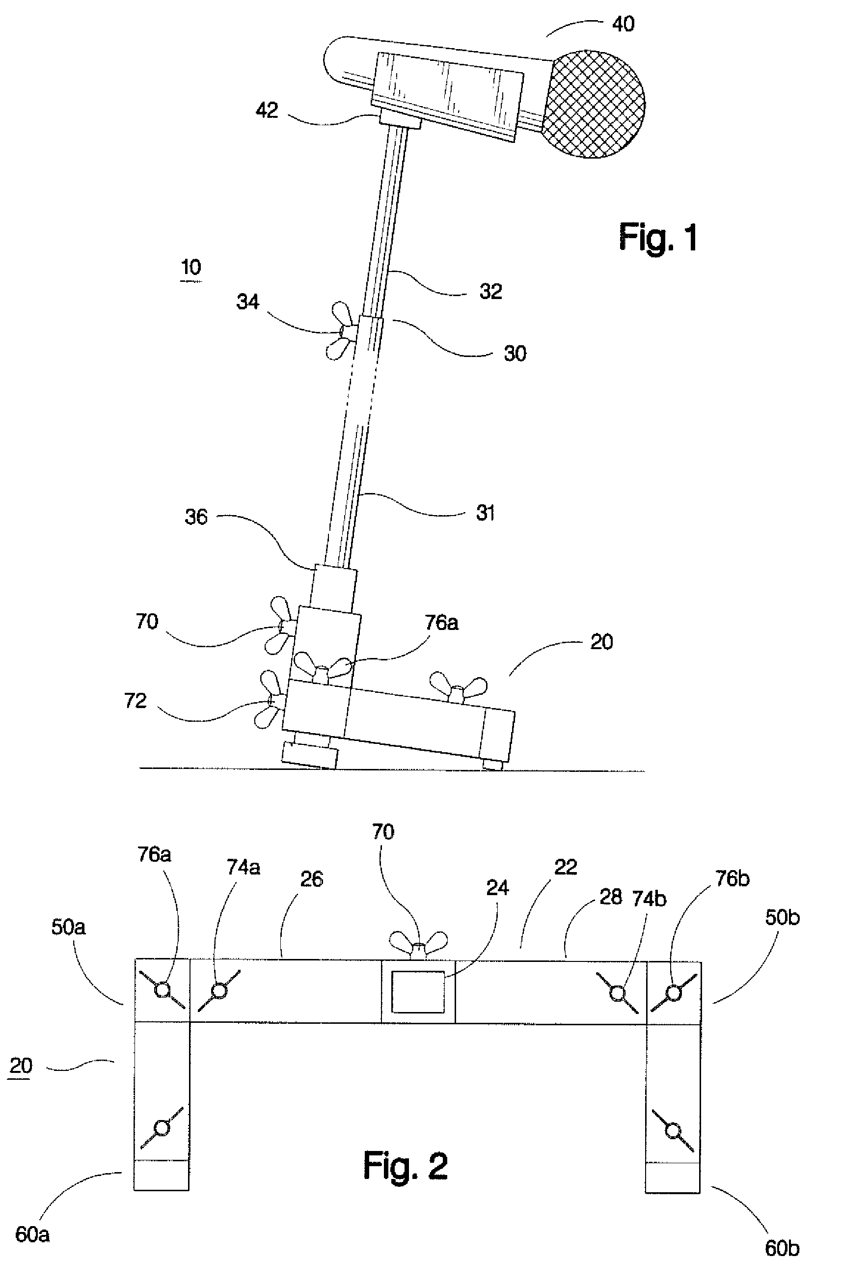
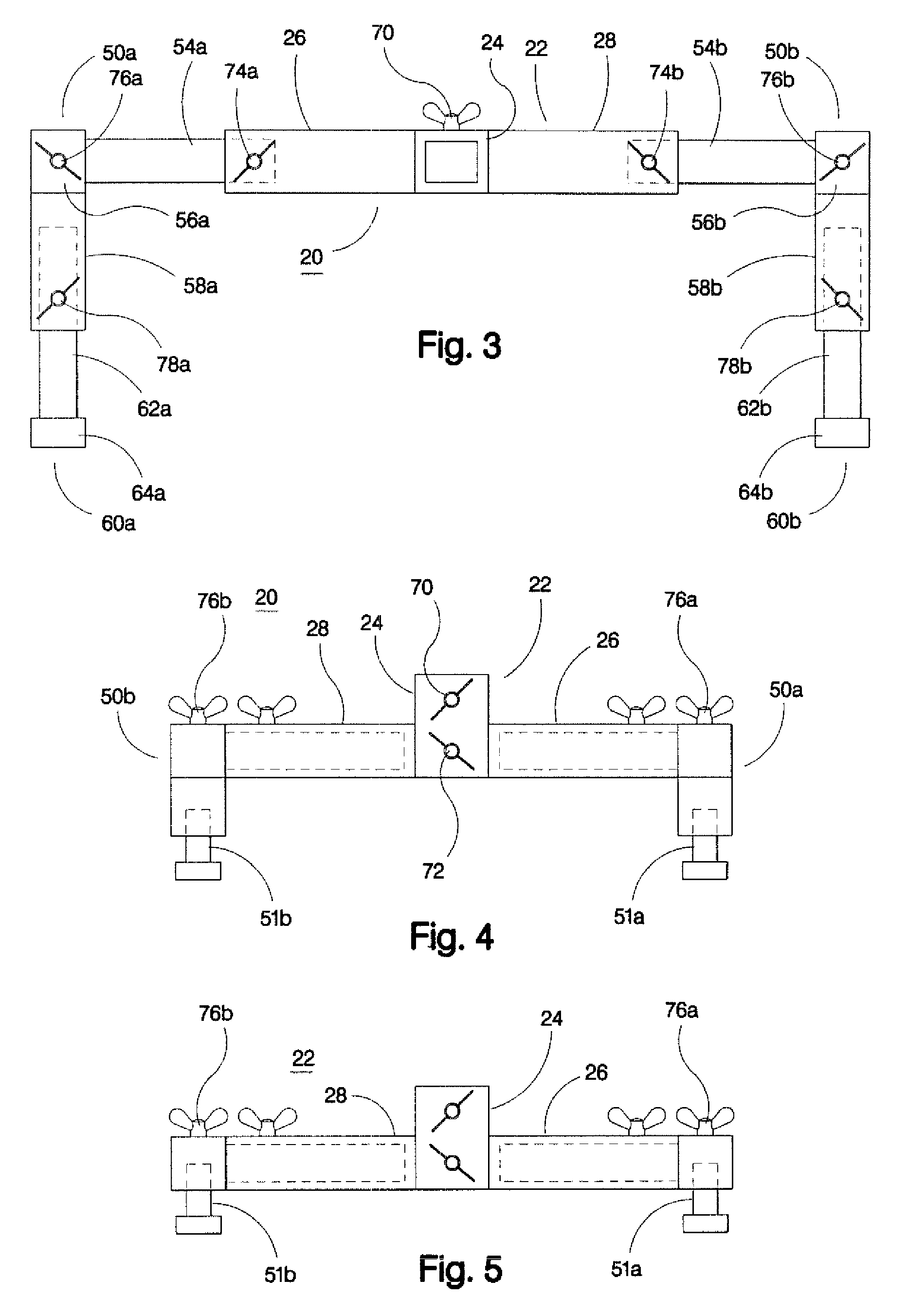
[0074]It is frequently necessary or desirable to situate control pedals and other control equipment for loud speakers and other musical, performance and special effects equipment directly in front of a performer, which performer usually is also using a microphone or the like in his or her musical or other artistic performance. In a very large music hall or similar performing environment, there are usually sound men and other technical personnel to handle the operation of sound equipment, modify its effects from time to time as necessary,...


PUM


Abstract

A stand for holding a musical accessory at a convenient level having a base comprised of a plurality of adjustable telescoping members forming a U-shape base support, which can be adjusted to extend around other equipment in a crowded stage area, thereby conserving space and enabling the stand to be conveniently situated closely together with such other equipment, and in addition being used as an instrument and equipment support stand that can be compacted into a convenient small package for purposes of storage and transport. A structure for folding for carrying and transportation is particularly disclosed.

Description

CROSS REFERENCE TO RELATED APPLICATION[0001]This application is a Continuation-in-Part application based upon and taking priority from U.S. patent application Ser. No. 11 / 183,558, filed on Jul. 18, 2005 and assigned U.S. Pat. No. 7,176,366 which was based upon and took priority from U.S. patent application Ser. No. 10 / 823,092, filed on Apr. 13, 2004, now U.S. Pat. No. 7,131,615 which was based upon and took priority from U.S. patent application Ser. No. 10 / 145,051 filed on May 14, 2002, now U.S. Pat. No. 6,720,490.BACKGROUND OF THE INVENTION[0002]1. Field of the Invention[0003]The present invention relates to equipment stands used by musicians, and more particularly to stands for microphones, music, instruments and amplifiers, and more particularly still to a stand having a horizontally adjustable base particularly for use on a crowded stage or performing area and capable of extending around floor supported musical equipment as well as supporting various musical instruments and musi...

Claims


Application Information

Patent Timeline
Patent Type & Authority Patents(United States)
IPC IPC(8): G10D9/00
CPCA47B81/00G10G5/00H04R1/083
Inventor BRUCE, HARPER M.
Owner BRUCE HARPER M
Why Eureka
Try Eureka