
Support for small-diameter filamentary elements and a bundle of filamentary elements held together by the support

a technology of filamentary elements and support, which is applied in the direction of insulated conductors, cables, instruments, etc., can solve problems such as harmful thermal stresses, and achieve the effect of facilitating access

Inactive Publication Date: 2003-06-17
ALCATEL LUCENT SAS
View PDF15 Cites 46 Cited by
  • Summary
  • Abstract
  • Description
  • Claims
  • Application Information

AI Technical Summary

Benefits of technology

An object of the invention is to hold small-diameter filamentary elements together such as optical fibers or electrical coaxial cables using means that facilitate access to each filamentary element and, where appropriate, enable different bundles and filamentary elements to be identified.

Problems solved by technology

Furthermore, polymerization of the ribbon resin is an exothermic reaction that can give rise to harmful thermal stresses in the optical fibers embedded in the resin.

Method used


Image

  • Support for small-diameter filamentary elements and a bundle of filamentary elements held together by the support
  • Support for small-diameter filamentary elements and a bundle of filamentary elements held together by the support

Examples


first embodiment

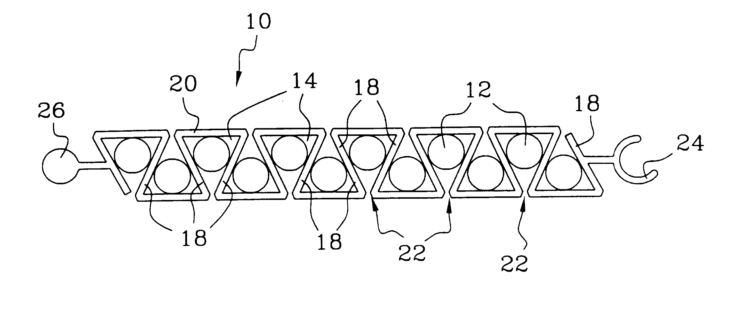
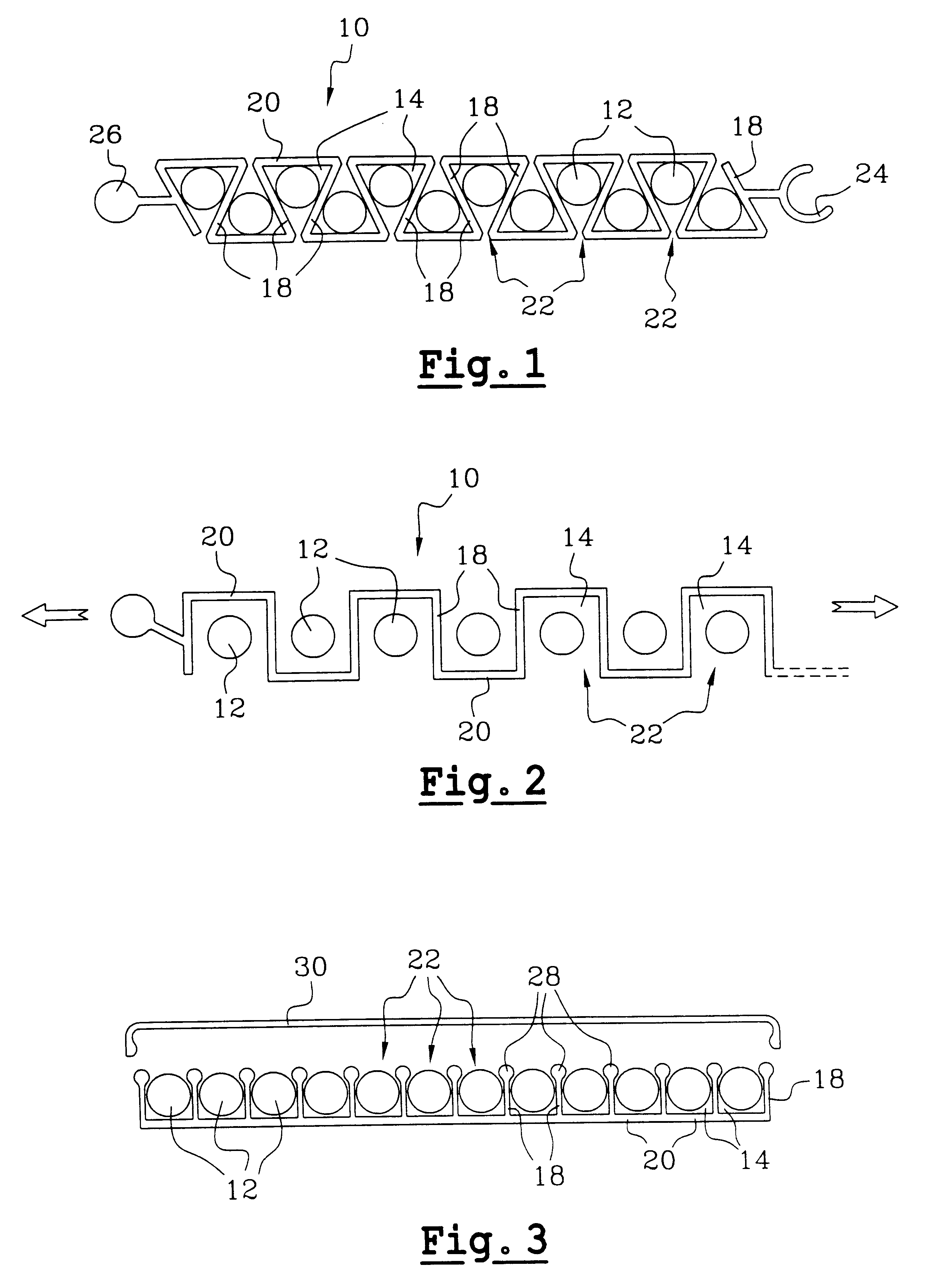
FIGS. 1 and 2 show a support 10 constituting the invention for supporting small-diameter filamentary elements 12 having a diameter that is less than or equal to one millimeter.

In the example shown, the filamentary elements 12 are conventional optical fibers for use in a telecommunications network, for example. The optical fibers 12 are made out of an inorganic material or a synthetic material. An inorganic type optical fiber comprises, for example, a doped silica core coated in inorganic cladding and an organic sheath that commonly comprises two layers of synthetic material.

In a variant, the filamentary elements 12 can be constituted by electrical coaxial cables of the kind commonly used in telecommunications installations or in medical equipment.

The support 10 is preferably designed to carry a dozen filamentary elements 12. Nevertheless, the number of filamentary elements 12 carried by the support can be less than or greater than one dozen.

The support 10 is generally plane and elon...

second embodiment

FIG. 3 shows a support 10 for filamentary elements 12. In this embodiment, the longitudinal openings 22 of successive channels 14 all open out into the same face of the support 10.

Each longitudinal wall 18 has its free edge provided with a bead 28 for retaining the filamentary elements 12.

The face of the support into which the longitudinal openings 22 of the channels 14 open out is preferably provided with a cover 30 for closing the channels 14.

The advantages of the invention include that of making it possible to hold together small-diameter filamentary embodiments such as optical fibers or coaxial cables using means that give easy access to each filamentary element 12.

The channels 14 of the support are of dimensions that are adapted specifically to retain either inorganic optical fibers usually having a diameter of 250 .mu.m, or else synthetic type optical fibers usually having a diameter of about 500 .mu.m.

The support of the invention can also hold together coaxial cables having d...


PUM


Abstract

The filamentary elements are of a diameter that is less than or equal to 1 millimeter. The support comprises longitudinal channels each intended to house a respective filamentary element, each channel being defined by two longitudinal walls interconnected by a web and defining a longitudinal channel opening, the width of said longitudinal opening being variable by elastically deforming the longitudinal walls between an access configuration giving access to the channel enabling a filamentary element to pass through said opening and a retaining configuration for retaining a filamentary element in the channel. The filamentary elements are selected from optical fibers and electrical coaxial cables.

Description

The present invention relates to a support for small-diameter filamentary elements and to a bundle of filamentary elements interconnected by the support.The invention applies in particular to installations comprising bundles of optical fibers or of electrical coaxial cables of small diameter.Amongst the optical fibers commonly used in a cable telecommunications network, it is common practice to distinguish between inorganic optical fibers, generally made of silica, and optical fibers made of synthetic material.In general, an inorganic optical fiber comprises a core of doped silica coated in intermediate inorganic optical cladding and in a peripheral organic sheath made of synthetic material. In general, the peripheral sheath is constituted by a flexible first sheath coated in a hard second sheath. An optical fiber of this type commonly has a diameter of 250 micrometers (.mu.m).An optical fiber of synthetic material is commonly of larger diameter than an inorganic optical fiber. A co...

Claims


Application Information

Patent Timeline
Patent Type & Authority Patents(United States)
IPC IPC(8): G02B6/36G02B6/44F16B2/22F16B5/00F16B5/06G02B6/00F16B7/04H02G3/04H02G3/30H05K7/00
CPCG02B6/4459Y10S439/942G02B6/4471
Inventor GALAJ, STANISLASVANPOULLE, SOPHIEANDRIEU, XAVIER
Owner ALCATEL LUCENT SAS
Learn More