Miter box

a technology of miter box and box body, which is applied in the field of miter box, can solve the problems of inability to withstand, inconvenient cutting of materials, and additional work, and achieves the effect of improving the cutting efficiency of materials and reducing the number of miter boxes

Inactive Publication Date: 2003-06-24
RYAN RICHARD P
View PDF17 Cites 10 Cited by
  • Summary
  • Abstract
  • Description
  • Claims
  • Application Information

AI Technical Summary

Problems solved by technology

On construction sites the reciprocating saw is one of the most commonly used saws but it's mainly suitable for demolition work because of its ability to reach into small places and its inability to make accurate cuts.
When the work piece is out of position unfortunately this may be the only saw that will work.
This will lead to additional work.
Craftsmen have tried to alleviate this pr

Method used


Image

  • Miter box
  • Miter box
  • Miter box

Examples


Embodiment Construction

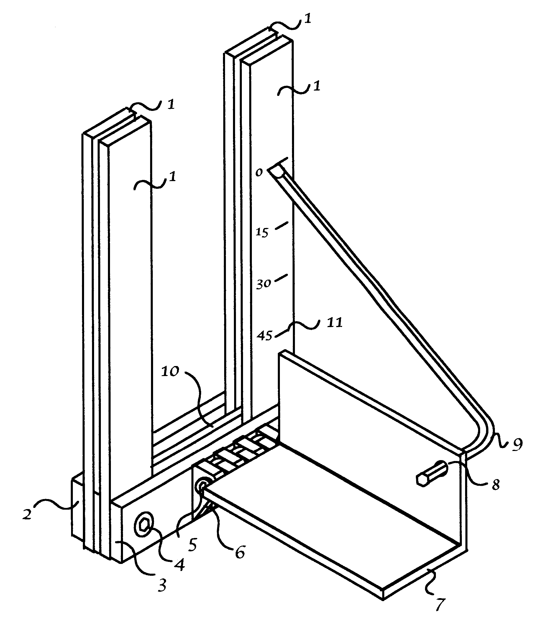
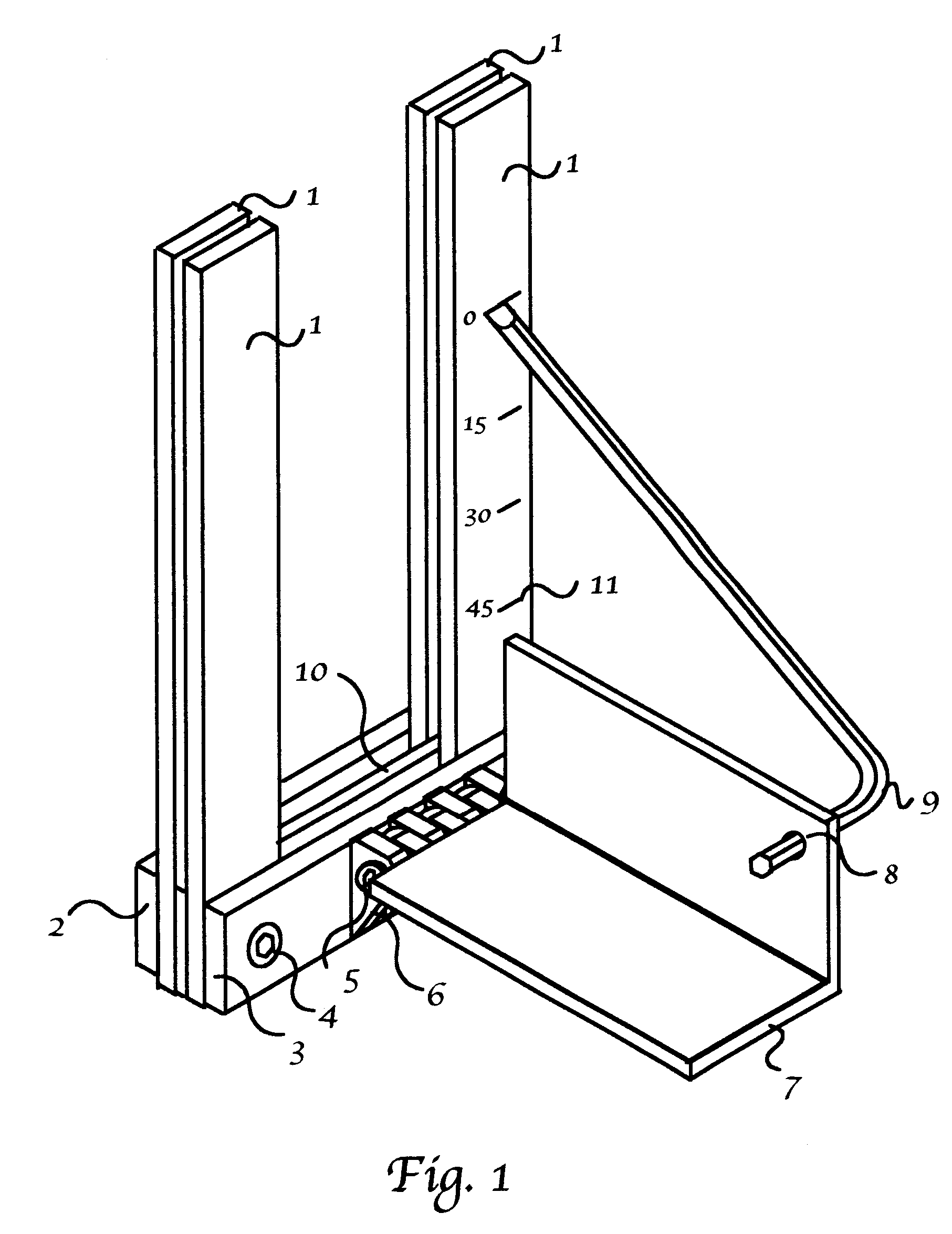
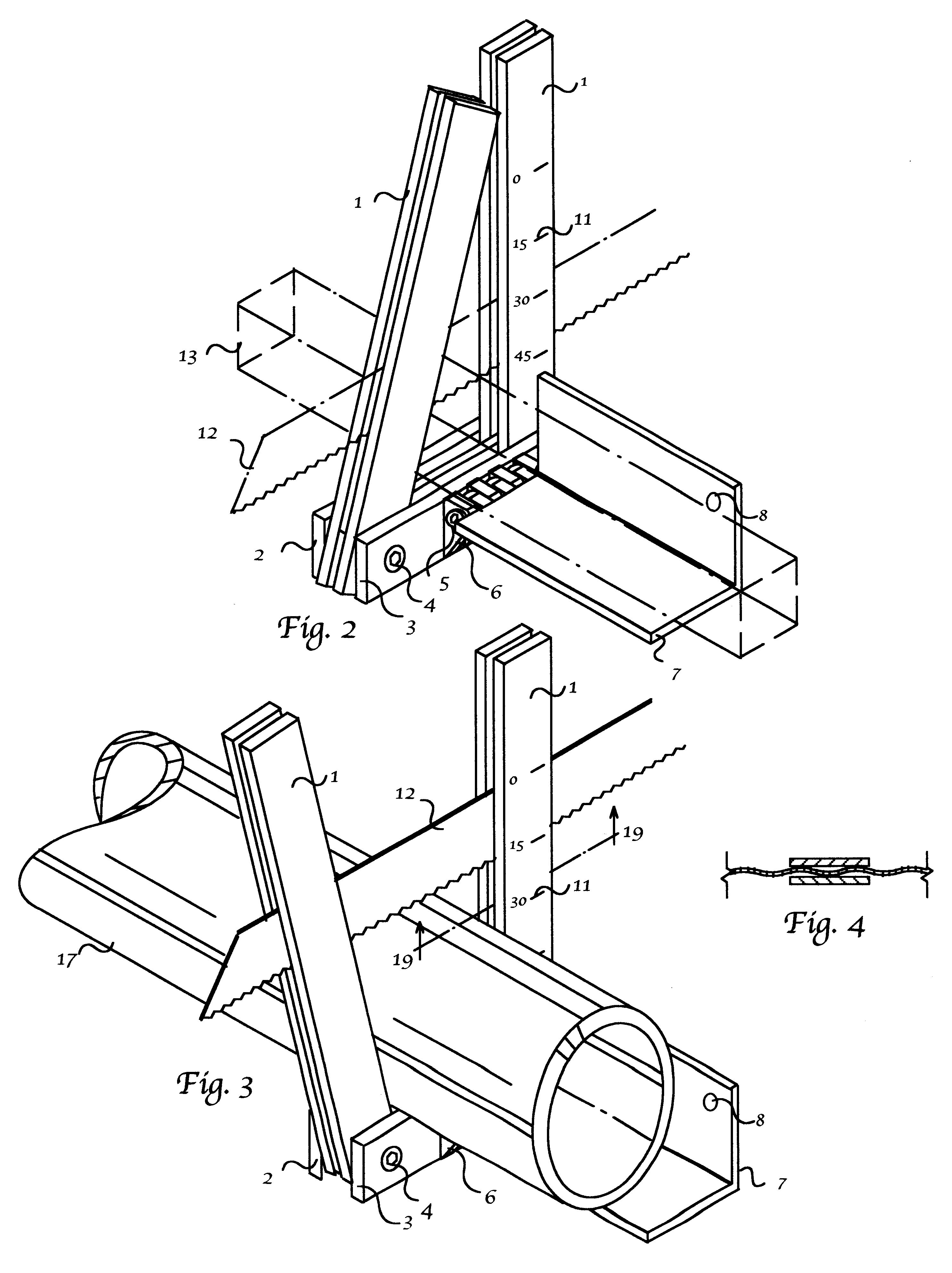
A preferred embodiment of the closure of the present invention is illustrated in FIG. 1. A pair of parallel saw guides 1 made of hard or harden material, spaced to accommodate a saw blade 12 and an opposing pair of parallel saw guides 1 also spaced to accommodate a saw blade 12. A single horizontal spacer bar 10 is inserted at the base of and in between both parallel saw guide 1. A horizontal back plate 2 and a horizontal front plate 3 through the use of threaded bolt 4 compresses all parallel saw guides 1 and horizontal spacer bar 10 to hold the parallel saw guides 1 in place. A table 7 is hinged perpendicular and slightly above the horizontal front plate 3. The locking friction hinge 18 is a series of plates 6 with a threaded hinge pin 5. When the threaded hinge pin 5 is tightened, it compresses the hinge plates 6, holding the table 7 in place. A scale 11 as been included on one of parallel saw guides 1 so when an hex like wrench 9 is inserted through a hole in the table 8 and pre...


PUM

PropertyMeasurementUnit
Lengthaaaaaaaaaa
Angleaaaaaaaaaa

Abstract

A saw blade guide which can be attached directly to work piece and will guide a reciprocating blade or band saw blade at a predetermined angle through the work piece.

Description

1. Field of the InventionThe present invention relates to a miter box, and more particularly, to a portable miter box specially designed for limited access and adapted for use with band saws and reciprocating saws.2. Description of the Prior ArtOn construction sites the reciprocating saw is one of the most commonly used saws but it's mainly suitable for demolition work because of its ability to reach into small places and its inability to make accurate cuts. When the work piece is out of position unfortunately this may be the only saw that will work. This will lead to additional work. The craftsmen must sand, grind or even do additional welding to correct the inaccurate cut.Craftsmen have tried to alleviate this problem through the use of miter boxes but problems with the prior miter boxes is inability to withstand the heavy forces of a reciprocal saw and still remain portable and compact enough to allow cutting of a work piece that is out of position.The object and feature of the p...

Claims


Application Information

Patent Timeline
IPC IPC(8): B27G5/02B27G5/00
CPCB27G5/02Y10T83/6955Y10T83/697Y10T83/8773
Inventor RYAN, RICHARD P.
Owner RYAN RICHARD P
Why Eureka
Try Eureka